




Although batterie agli ioni di litio have the highest densità di energia, possono essere vulnerabili a condizioni che potrebbero danneggiare la batteria. Ecco perché abbiamo bisogno di un sistema di gestione della batteria per aiutare a prevenire condizioni così dannose.
A properly designed BMS is the reason a lithium-ion pack can deliver thousands of cycles instead of failing early or catching fire.
Transparency Market Research projects the global BMS market to grow from $9.4 billion in 2025 to $52.4 billion by 2036, a figure that covers the full BMS hardware and software stack rather than just the battery pack itself, and market-size estimates vary across research firms depending on what’s included in scope.
Even accounting for that variance, understanding what a BMS does has become essential knowledge for anyone specifying, purchasing, or integrating battery systems.
- A BMS monitors voltage, current, and temperature at the cell level to prevent overcharge, over-discharge, and thermal runaway.
- The four main architectures are centralized, modular, primary/subordinate, and distributed, each with different trade-offs for scalability and fault isolation.
- State of Charge (SOC) estimation accuracy depends on which algorithm the BMS uses: OCV lookup is simple but requires rest time; Kalman filters are more accurate in real-time operation.
- Industrial BMS units communicate over CAN bus, Modbus RTU, or RS485 for integration with inverters, SCADA systems, and chargers.
- Certifications depend on the application: UL 1973 and IEC 62619 apply to stationary and industrial packs, while UL 2054 and IEC 62133-2 apply to portable electronics. UN 38.3 governs transport safety with 8 abuse tests.
What Is a Battery Management System?
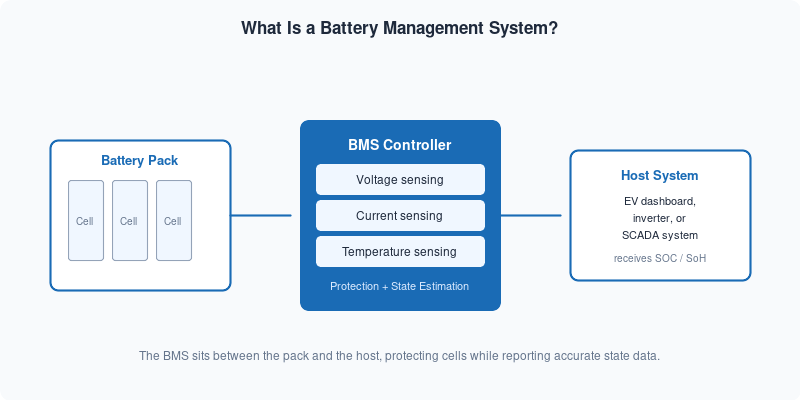
A battery management system is an electronic controller that sits between a battery pack and the devices or infrastructure connected to it. It reads data from sensors embedded in the pack, makes real-time decisions based on that data, and communicates status to external systems.
The core purpose is to protect the cells from conditions that shorten life or cause failure, while also providing accurate state information so the host system can use the battery efficiently.
Modern BMS designs do more than simple protection switching. They run continuous algorithms to estimate how much energy remains in the pack (State of Charge) and how much capacity the pack has lost over its lifetime (State of Health).
That information is what allows an EV dashboard to show a reliable range estimate, or what allows a data-center UPS to trigger an alert before a cell degrades to the point of failure.
Why Do Lithium-Ion Batteries Need a BMS?
Lithium battery incidents in U.S. aviation reached 93 cases in 2025, a 4.5% increase from the prior year, according to FAA incident data reported byLion Laboratories, February 2026.
The underlying issue is thermal runaway, which occurs when internal temperatures exceed the threshold where exothermic reactions become self-sustaining. Once thermal runaway begins in a single cell, it can propagate through the pack at speeds that overwhelm passive cooling, causing temperatures that climb into the hundreds of degrees Celsius within minutes.
A BMS prevents these conditions by monitoring each cell group and cutting power the moment voltage, current, or temperature approaches unsafe limits.
Without this layer of control, lithium-ion cells are vulnerable to overcharge (plating lithium metal on the anode), over-discharge (dissolving copper from current collectors), and short circuits from internal dendrite growth. These failure modes don’t announce themselves in advance. A cell can appear to function normally right up until the point of failure.
Beyond safety, a BMS is what makes high-density lithium chemistry practical for commercial use. The same energy density that makes lithium attractive also makes it intolerant of abuse conditions that older chemistries like lead-acid could survive. The BMS is the engineering layer that closes that gap.
Core Functions of a Battery Management System
Every BMS performs a set of essential tasks regardless of architecture or application. These functions define what the BMS is responsible for during normal operation.
Cell Monitoring
The BMS measures voltage, current, and temperature across the pack. In series-connected configurations, voltage is sampled at each cell or cell group to detect imbalances or outliers. Current is measured at the pack level using a precision shunt resistor or Hall effect sensor. Temperature sensors are distributed throughout the pack to catch localized hot spots before they spread.
Protection Switching
When a monitored parameter crosses a threshold, the BMS opens MOSFETs or contactors to interrupt current flow. There are typically separate thresholds for warning and for hard cutoff, so the system can alert the host before taking protective action. This prevents nuisance trips while still catching genuine fault conditions quickly enough to prevent damage.
Bilanciamento delle cellule
Cells in series diverge over time because manufacturing tolerances, temperature gradients, and usage patterns cause each cell to age slightly differently. A BMS balances the pack by dissipating excess energy from higher-voltage cells (passive balancing) or redistributing it to lower-voltage cells (active balancing).
Without balancing, the pack’s usable capacity is limited by its weakest cell, and cycle life shortens as the imbalance compounds over time.
For LFP packs specifically, see our guide to LFP cell balancing.
State Estimation
The BMS continuously estimates State of Charge (SOC) and State of Health (SoH): the two numbers that tell you how much energy is available now, and how much capacity the pack has retained over its lifetime. These estimates feed the host system’s display, control logic, and maintenance scheduling. The accuracy of these estimates depends heavily on which algorithm the BMS uses, which is covered in detail in the next section.
Communication and Reporting
A BMS sends real-time data to external systems through standardized communication interfaces. In automotive and industrial applications this typically means CAN bus or RS485/Modbus. The BMS transmits pack voltage, current, temperature, SOC, SoH, fault status, and cell-level data to chargers, inverters, and control systems. This communication layer is what turns a battery pack from an isolated component into an integrated element of a larger system.
The Four BMS Architecture Types
How a BMS is physically structured across the pack determines its scalability, fault tolerance, and wiring complexity. There are four recognized architecture types, and the right choice depends on pack size and application requirements.
If you’re new to pack terminology, our guide to battery cell vs. module vs. pack covers the basic building blocks first.
Centralized BMS
A single board handles all monitoring, protection, and communication for the entire pack. Centralized designs are common in small to medium packs where simplicity and low cost matter more than scalability.
The main limitation is that a single hardware failure affects the whole pack, and wire harnesses get complex in large configurations.
Topologia BMS modulare
The pack is divided into modules, each with its own BMS board that handles local monitoring and cell balancing. A master controller collects data from all modules and handles system-level functions.
This approach scales well to large packs and makes field replacement straightforward: replace a faulty module board without touching the rest of the system.
BMS primario/subordinato
One master BMS unit communicates with multiple subordinate units distributed through the pack. The subordinates handle local measurement and balancing; the master handles protection logic, communication, and state estimation.
This architecture is common in battery energy storage systems (BESS) and EV applications where hundreds of cells need coordinated management.
Architettura BMS distribuita
Each cell or cell group gets its own small monitor chip with communication capability. These chips report to a central controller over a daisy-chain bus. Distributed designs offer the most granular cell visibility and the shortest sensor wire runs, at the cost of higher per-cell component count.
They’re used in high-end EV packs and aerospace applications where per-cell visibility justifies the cost.
SOC and SoH Estimation: How a BMS Knows What’s Left in the Battery
State of Charge estimation is the hardest problem a BMS solves.
Unlike a fuel tank, you can’t directly measure how much energy is stored in a lithium-ion cell. You have to infer it from measurable signals. The method used determines how accurate the BMS is across temperature extremes, aging, and dynamic load conditions.
Three approaches are in widespread use, each with different accuracy, computational requirements, and failure modes.
Open-Circuit Voltage (OCV) Lookup
The simplest method. At rest, the cell voltage follows a predictable curve that maps to a specific SOC level. The BMS reads the open-circuit voltage after a rest period and looks up the corresponding SOC in a stored table.
OCV lookup is accurate when the cell has had time to equilibrate (typically several minutes to hours), but it cannot be used during active charge or discharge because load current shifts the apparent voltage away from the true equilibrium point. Temperature also shifts the OCV-to-SOC relationship, so well-implemented systems use temperature-compensated lookup tables.
OCV is commonly used at startup, or to recalibrate an ongoing estimate after an extended rest.
Coulomb Counting (Ampere-Hour Integration)
The BMS integrates the current flowing in and out of the pack over time. If a fully charged pack has a known capacity and you track how many amp-hours have flowed out, you can calculate remaining SOC. Coulomb counting is simple to implement and works continuously during operation.
The problem is drift: small measurement errors in current sensing accumulate over time. Temperature affects coulombic efficiency, meaning not all charge put in comes back out. And if the starting SOC estimate is wrong, the error carries forward indefinitely.
Most BMS designs use Coulomb counting as the primary real-time estimator but periodically recalibrate it using OCV measurements at rest.
Kalman Filter Methods
Kalman filtering treats SOC estimation as a state-estimation problem. The filter uses a mathematical model of the battery (typically an equivalent circuit model with resistors and capacitors representing internal dynamics) plus real-time measurements of voltage and current to produce a statistically optimal SOC estimate. Crucially, it also produces a confidence interval, so the BMS knows not just the estimate but how reliable it is.
The Extended Kalman Filter (EKF) handles the nonlinear relationship between SOC and cell voltage by linearizing the battery model at each time step. The Unscented Kalman Filter (UKF) uses a different approach called sigma-point sampling that handles nonlinearity more accurately without requiring the linearization step, at somewhat higher computational cost.
For industrial packs where long-term accuracy matters, the UKF outperforms the EKF, particularly at the ends of the charge curve where OCV sensitivity is low. These accuracy figures come from controlled bench testing; real-world performance is typically somewhat lower once sensor drift, cell aging, and temperature swings are factored in, which is why most production BMS designs pair the filter with periodic recalibration rather than relying on the model alone.
Recent research (2025-2026) has focused on dual-estimator architectures that run simultaneous Kalman filters for SOC and SoH, so the battery model updates itself as the pack ages, maintaining accuracy over thousands of cycles. Machine learning integration is also active in research, with neural networks used to model the highly nonlinear OCV relationship at low temperatures where classical models struggle.
State of Health (SoH) Estimation
SoH quantifies how much capacity the pack has retained relative to its rated new condition. A pack at 100% SoH holds its full rated capacity; at 80% SoH it holds 80%. Most manufacturers define end-of-life at 80% SoH, though some applications tolerate lower.
SoH is harder to estimate than SOC because degradation accumulates slowly over months and years. Common methods include cycle counting with weighted depth-of-discharge, capacity measurement during full charge-discharge events, and impedance spectroscopy where the BMS measures internal resistance as a proxy for cell aging.
Impedance-based SoH is particularly useful because internal resistance increases measurably as cells age, and the BMS can track this continuously without requiring a full discharge cycle.
Communication Protocols: How a BMS Talks to the Rest of the System
A BMS that can’t communicate its status is only half a product.
Industrial and commercial battery systems connect their BMS to chargers, inverters, SCADA platforms, and building management systems through standardized communication protocols.
Three protocols dominate: CAN bus, RS485, and Modbus RTU over RS485. or a deeper comparison of when to use each, see our guide to battery communication protocol options.
CAN Bus
CAN bus (Controller Area Network, ISO 11898) was developed for automotive environments and remains the dominant protocol for EV battery management. Its key advantage is native fault tolerance: every node on the bus can detect errors and request retransmission without a central coordinator.
Message priority is baked into the protocol through arbitration, so high-priority safety messages (like a thermal fault alarm) always reach the master controller before lower-priority status updates. CAN bus supports up to 128 nodes and runs at speeds up to 1 Mbps.
It’s the right choice when the BMS needs to integrate with a vehicle’s powertrain control module or where millisecond-level response to fault conditions matters.
RS485
RS485 uses differential signaling: the voltage difference between two wires carries the signal, not a reference to ground. This makes it highly resistant to electrical noise in industrial environments.
RS485 cables can run 1,200 meters, making it practical for large battery rooms where the BMS controller is physically distant from the pack. Up to 32 nodes can share a single RS485 segment; repeaters extend that number.
RS485 is common in stationary energy storage installations, solar-plus-storage systems, and telecommunications backup power. It doesn’t define a higher-level protocol on its own, which is why Modbus over RS485 became the standard combination for industrial BMS applications.
Modbus RTU
Modbus is the application-layer protocol that runs on top of RS485 in most industrial BMS deployments. It defines a register map: the BMS exposes its measurements and status as numbered registers that any Modbus-capable device can read or write.
A SCADA system can poll pack voltage from register 0x0001, total current from 0x0002, and fault status from 0x0010. The exact addresses depend on the BMS manufacturer’s register map, which reputable manufacturers publish in their technical documentation.
Modbus RTU supports up to 247 logical addresses per network and is supported natively by virtually every industrial PLC, inverter, and building management system made in the past 30 years.
Note that this address limit describes the protocol layer, not the physical wiring: the underlying RS485 segment those addresses run on still tops out at 32 nodes without repeaters, so a network with more than 32 devices needs repeaters or a multi-segment topology even though all 247 Modbus addresses remain available for use.
CUSTOM BMS ENGINEERING
Need a BMS Matched to Your Battery Pack?
Share your battery chemistry, voltage, current, operating environment and communication requirements. Our engineers can help define the BMS architecture, protection strategy and CAN or RS485 integration.
Discuti i requisiti della batteriaSafety Certifications and Standards That Govern BMS Performance
There is no certification that tests a BMS in isolation. Instead, the BMS is evaluated as part of the complete battery pack it manages, and a poorly designed BMS is often the reason a pack fails these tests.
The standards below apply to the finished pack, but they tell you exactly what a BMS actually needs to get right. Which standard applies depends heavily on the application: portable electronics, stationary energy storage, and air transport each have their own requirements, and conflating them is a common mistake when evaluating vendors.
UL 2054 and UL 1973: Portable vs. Stationary Packs
UL 2054 is the North American standard for household and commercial battery packs, meaning portable products like power tools, e-bikes, and consumer electronics. It covers both the cells and the BMS that manages them, requiring testing for overcharge protection, short-circuit protection, abnormal charging, crush, impact, and thermal abuse.
UL 1973 is the standard that actually governs stationary and industrial energy storage systems, including battery energy storage systems (BESS) and light electric rail applications. For a BESS or industrial BMS vendor, UL 1973 certification matters more than UL 2054.
Facilities integrating large-format stationary storage should also ask about UL 9540A, which specifically tests fire propagation behavior at the cell, module, unit, and installation level, a distinct concern from pack-level abuse testing.
IEC 62133-2 and IEC 62619: International Safety Standards
IEC 62133-2 is the international equivalent of UL 2054, covering secondary lithium cells and batteries for portable applications. It defines tests for external short circuit, overcharge, forced discharge, thermal abuse, and crush.
IEC 62619 is the standard that matters for stationary and industrial lithium-ion systems internationally, playing the same role for industrial packs that IEC 62133-2 plays for portable ones. Manufacturers targeting BESS or industrial deployments in international markets should hold IEC 62619, not just IEC 62133-2. See our breakdown of UN 38.3 vs. IEC 62133 vs. IEC 62619 for how these standards relate to each other.
UN 38.3: Transport Safety
UN 38.3 is not a product safety standard but a transport safety protocol. It consists of eight abuse tests designed to verify that a battery can survive the mechanical and thermal conditions of air, sea, and ground transport without venting, leaking, rupturing, or igniting. The eight tests include altitude simulation (low pressure), thermal cycling, vibration, shock, external short circuit, impact, overcharge, and forced discharge.
UN 38.3 test summaries don’t need to accompany the physical shipment but must be accessible on request.
Under IATA’s updated Battery Guidance Document, effective January 1, 2026, lithium-ion batteries packed with equipment (Packing Instruction 966) must ship at no more than 30% of rated capacity unless the shipper has State approval to exceed that limit.
This is narrower than a blanket rule: it applies specifically to batteries packed with equipment rather than all lithium shipments, and requirements vary by packing instruction and battery category, so shippers should confirm the applicable limit with their carrier rather than assume a single threshold covers every shipment type.
When evaluating a BMS vendor, verify which certifications they hold and confirm that the certified configuration matches the actual product being purchased. Some manufacturers certify a reference design but ship variations that weren’t part of the certification test. Ask for the certificate number and verify it directly with the certification body.
Benefits of a Properly Designed BMS
The measurable benefits of a quality BMS show up in pack longevity, uptime, and total cost of ownership.
A well-implemented BMS extends cycle life by preventing the cell-damaging conditions that accelerate degradation: overcharge, deep discharge, high-rate cycling at temperature extremes, and long periods at full charge or full discharge. Learn more about what drives battery cycle life and how to extend it.
In Holo Battery’s own field deployments, battery packs with active balancing and temperature-aware SOC management have reached 3,000 to 5,000 cycles before hitting 80% SoH at moderate depth-of-discharge and room-temperature operation, while comparable packs with simple overvoltage cutoffs often fail before 1,500 cycles under the same duty cycle. Results vary with C-rate, depth-of-discharge, and ambient temperature, so treat these as directional rather than guaranteed figures for any specific application.
Operational benefits include predictable maintenance windows (because SoH tracking gives advance warning of capacity loss), reduced insurance costs (certified BMS designs lower the assessed fire risk), and simpler integration with external systems through standardized communication.
For commercial and industrial users, the BMS is what transforms a battery pack from a liability requiring constant supervision into a predictable, maintainable component that integrates cleanly with existing infrastructure.
Holo Battery’s BMS: What We Test and Certify
Holo Battery designs and manufactures BMS hardware for commercial and industrial lithium-ion packs. Every Holo Battery BMS is tested to UL 1973 and IEC 62619 requirements, the standards that apply to stationary and industrial systems, and all packs ship with UN 38.3 test summaries for transport.
Our BMS architecture uses a modular primary/subordinate design with cell-level voltage sampling at 1 mV resolution, NTC thermistors at every module, and a UKF-based SOC estimator calibrated across the full operating temperature range of -20°C to +60°C.
Communication interfaces include CAN bus (ISO 11898, up to 1 Mbps) and RS485/Modbus RTU, both exposed on the same connector. This means our packs can integrate directly with EV powertrains, solar inverters, SCADA platforms, and building energy management systems without an additional protocol converter.
The onboard protection stack covers overvoltage, undervoltage, overcurrent (charge and discharge), short circuit, and over-temperature on both charge and discharge paths. Short-circuit response time is under 200 microseconds.
The BMS logs fault events with timestamps to on-board flash memory, so post-event analysis is possible without requiring continuous external data logging.
Frequently Asked Questions About Battery Management Systems
What’s the difference between active and passive cell balancing?
Passive balancing dissipates excess energy from higher-voltage cells as heat. Active balancing moves that energy to lower-voltage cells instead, which is more efficient but costs more to implement. Large packs benefit most from active balancing; smaller packs with mild imbalance usually stick with passive.
How accurate is SOC estimation in a real BMS?
It depends on the algorithm. Coulomb counting alone drifts to ±10–15% error over time, while a temperature-compensated EKF holds ±3–5% and UKF implementations reach ±2–3% in controlled tests. The most accurate systems combine Coulomb counting with periodic recalibration and update their battery model as cells age.
Can I use a BMS with LiFePO4 (LFP) batteries?
Yes, but it needs to be configured for LFP’s flat voltage curve, which makes OCV-based SOC estimation unreliable across most of the charge range. LFP cells also charge to 3.65V per cell and discharge to around 2.5V, versus 4.2V for NMC, so a BMS calibrated for NMC will misread an LFP pack and may trip protection prematurely.
What certifications should I require from a BMS vendor?
For stationary or industrial packs, require UL 1973 and IEC 62619. For portable products, UL 2054 and IEC 62133-2 apply instead. Any battery shipped by air needs UN 38.3. Always ask for the certificate number and verify it directly with the certification body, since some vendors certify one design but ship variants that were never tested.
What causes a BMS to fail, and how can I prevent it?
Common causes include moisture ingress, vibration damage to sense leads, MOSFET failure from sustained overcurrent, and firmware bugs that trigger false trips. Prevention comes down to an adequate IP rating for the environment, solid mechanical support for connectors and harnesses, and choosing a manufacturer that publishes derating and mean-time-between-failure data.
Conclusione
A battery management system is what makes lithium-ion chemistry safe and practical for real applications, controlling the risks that come with high energy density while keeping cells performing close to their rated life.
Getting it right means matching the architecture to pack size, choosing an estimation method accurate enough for the use case, aligning communication protocols with the host system, and confirming the certifications required for the target market.
If you’re evaluating BMS options or designing a custom battery system,contact Holo Battery’s engineering team to discuss your requirements.