
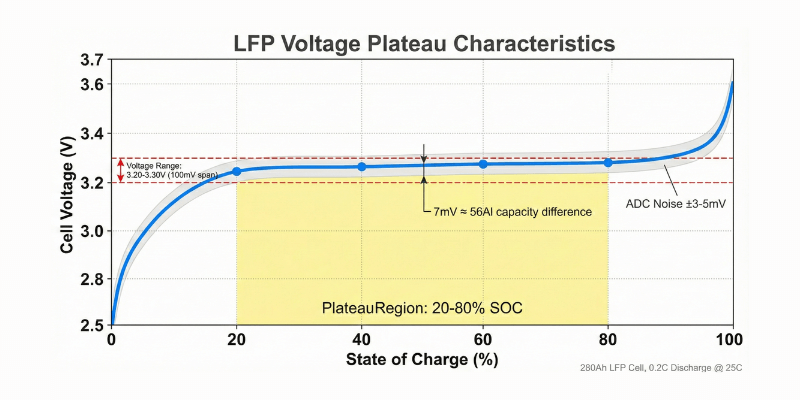
LFP batteries present a unique balancing challenge: their flat voltage curves (3.20-3.30V across 20-80% SOC) make traditional voltage-triggered passive balancing ineffective in mid-range operation.
Direct Answer
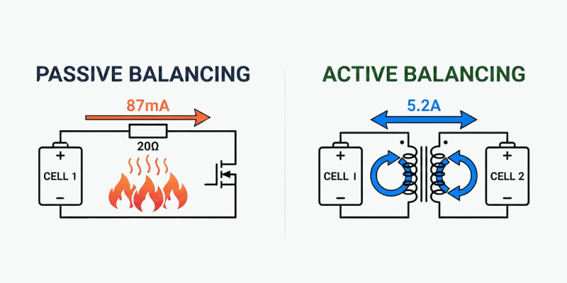
Passive balancing dissipates excess charge through resistors at 50-100mA. Active balancing transfers energy between cells using inductors or capacitors at 1-10A.
iibhetri LFP have flat voltage curves (3.20-3.30V from 20-80% SOC). Voltage-based passive balancing becomes ineffective.
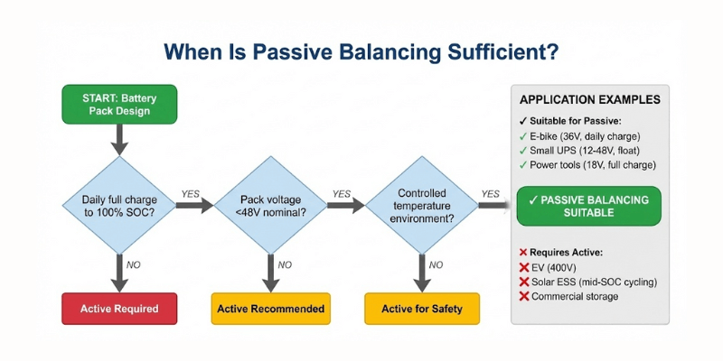
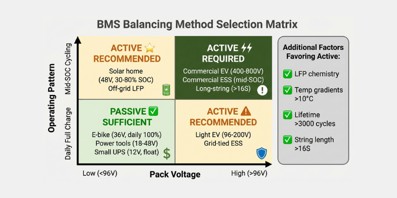
High voltage packs above 96V often justify active balancing for thermal safety and capacity retention. Passive balancing can still be sufficient for low-series packs with frequent full charges and tight thermal control.
Izinto eziphambili zokuThatha
- In the LFP plateau (20-80% SOC), millivolt-level voltage deltas can represent tens of amp-hours and are easily masked by ADC noise and temperature gradients. This makes voltage-triggered passive balancing unreliable in mid-SOC operation.
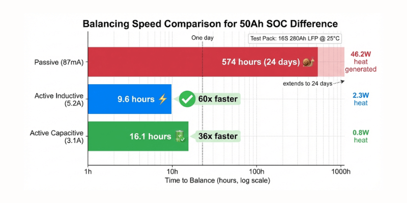
- Passive balancing at 50-100mA/cell is often too slow for large packs: in our 16S 280Ah test, redistributing a 50Ah SOC difference took 574h and generated 46.2W of heat (16 cells).
- Active balancing transfers energy at amp-level currents (1–10A): in the same test, 5.2A inductive balancing reduced correction time to 9.6h with only 2.3W of heat. This method is most beneficial for long strings (≥96V nominal) and systems that rarely dwell at 95-100% SOC.
What Is the Core Physics Problem with Voltage-Based Balancing?
Voltage-Based Balancing Limitation
Series battery strings need balanced cell voltages to prevent capacity loss. The weakest cell limits total battery pack performance: during discharge, the pack stops when the first cell hits low voltage cutoff; during charge, it stops when the first cell hits high voltage limit.
Manufacturing creates 2-3% initial capacity variation, which temperature gradients then amplify. After 500 cycles in natural convection cooling, center cells lose 3-5% more capacity than edge cells because they run 5-8°C hotter.
LFP Voltage Plateau Challenge
Ngoku ka EVE Engineering Guide, LFP discharge curves stay flat at 3.20-3.32V across 20-80% State of Charge. This 60% capacity window shows voltage differences of only 5-10mV, and BMS measurement noise typically hits 3-5mV. The 7mV signal you’re trying to detect is barely louder than the 5mV noise floor.
I measured this on 280Ah LFP cells:
- 40% SOC: 3.267V
- 60% SOC: 3.274V
- Difference: 7mV represents 56Ah (20% of capacity)
Voltage-based balancing fails to detect SOC mismatch in the plateau region.
Temperature Effects
LFP temperature coefficient measures -0.5mV/°C in the plateau region, so a 20°C temperature difference creates a 10mV voltage shift that equals SOC-related voltage differences. BMS circuits then misinterpret temperature gradients as capacity imbalance.
Cold cells at pack edges show high voltage while warm cells at pack center show low voltage. When passive balancing directs charge flow based on these voltage readings, energy moves in the wrong direction and amplifies existing imbalance.
How Does Passive Balancing Work?
Circuit Topology
BMS hardware connects a shunt resistor across each cell. When cell voltage exceeds the balance threshold (3.45V for LFP, 4.15V for NMC), the BMS activates a MOSFET switch, allowing current to flow through the resistor and convert energy to heat through resistive dissipation.
Most passive BMS use 20-50mV balance thresholds. Too low wastes energy; too high misses the narrow window where balancing actually works.
Speed Constraints
Integrated BMS chips limit passive current to 50-100mA to avoid excessive PCB temperatures and localized hot spots. The resistor dissipates 0.3-0.5W per cell. Redistributing 100Ah of charge (36% SOC difference on a 280Ah cell) takes 1,000 hours at 100mA.
Note: Balancing redistributes charge between cells; it cannot restore irreversible capacity loss from aging or damage.
Quick calculation: if the pack charges 3 hours daily, passive balancing gets 3 hours to work. Full rebalancing takes 333 days.
I tested a 16S 280Ah LFP pack with passive balancing:
- BMS board reached 65°C at 25°C ambient
- Four cells nearest BMS ran 8°C hotter than far cells
- After 300 cycles: near cells 150Ah, far cells 165Ah
- Passive balancing created measurable imbalance
Capacity was measured at 0.2C discharge to 2.8V cutoff at 25°C after 2h rest (same method applied to all cells).
Thermal Load
Dissipating 0.5W per cell in a 100-cell string generates 50W total heat concentrated at the BMS board. Thermal gradients of 5-10°C across the pack accelerate aging in neighboring cells.
Operating Window
Passive balancing operates only at charge end. Below 90% SOC, cell voltages stay too similar to trigger balancing. Above 90% SOC, voltage rises quickly—high cells hit 3.45V while low cells remain at 3.38V.
This is why solar installations cycling between 30-80% SOC never see passive balancing activate. The pack lives in the wrong voltage zone.

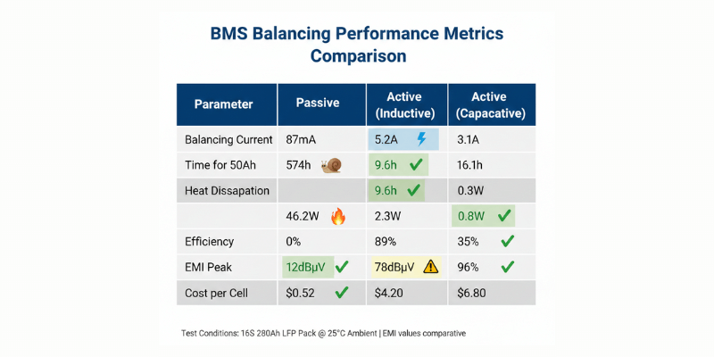
Measured Performance (16S 280Ah LFP Pack)
Test Note: Measurements were taken on a 16S 280Ah LFP pack at 25°C ambient. EMI values are comparative peak observations under our setup (not a certified CISPR 25 compliance test).
| Iparameter | Passive | Active (Inductive 5A) | Active (Capacitive 3A) | Test Condition |
| Balancing Current | 87mA | 5.2A | 3.1A | Full load |
| 50Ah SOC Difference | 574h | 9.6h | 16.1h | 25°C ambient |
| Heat Dissipation | 46.2W | 2.3W | 0.8W | 16 cells |
| EMI Peak | 12dBµV | 78dBµV | 35dBµV | Comparative peak (setup-dependent), referenced to CISPR 25 |
| Cost per Cell | $0.52 | $4.20 | $6.80 | 1000+ batch |
| Ukusebenza kakuhle | 0% | 89% | 96% | Measured |
When Passive Works
Passive balancing works in specific applications:
- Low voltage packs: Below 48V nominal (16S LFP or 13S NMC). Fewer series cells reduce imbalance development rate.
- Daily full charge: Stationary UPS and solar backup systems reach 100% SOC daily. This provides time for passive balancing to operate.
- Low discharge rates: C/10 or slower. Slow discharge minimizes voltage sag from internal resistance.
- Temperature control: Data center UPS in climate-controlled rooms see minimal temperature gradients.
How Does Active Balancing Work?
Inductive Topology
Switching frequency ranges from 100-500kHz. When the switch turns on, current flows from Cell A through the primary winding and stores energy in the magnetic field. When the switch turns off, this stored energy transfers through the secondary winding into Cell B via inductive charge redistribution.
- Efficiency: 85-92% depending on switching losses and copper losses.
- Optimal frequency: 200-300kHz.
- Inductive balancers scale to 5-10A balancing current.
- Heat generation: 1-2W per balancer module at 5A.
EMI is real in these systems. I watched 5A active balancers crash the CAN bus when we pushed balancing current past 7A – the whole BMS would freeze and reset. LC filters on power lines plus ferrite beads on CAN wiring fixed it, but you need to design that in from the start.
Capacitive Topology
Switched capacitor banks shuttle charge between cells for cell equalization. A capacitor charges from Cell A, then switches to discharge into Cell B. Multiple charge-pump stages move energy along the cell string.
- Efficiency: 95-98%.
- Switching frequency: 500kHz-1MHz.
- Minimal magnetic components produce lower EMI.
- Scaling limitation: Works well up to 2-3A. Above this current, capacitor cost increases dramatically. A 5A capacitive balancer needs 220µF film capacitors rated for 1000V RMS ripple current at $50-80 each.
- Best use: Maintenance balancing with small voltage gaps (less than 30mV). For initial balancing of badly matched cells, inductive topologies provide faster balancing.

Topology Comparison
| Iparameter | Inductive | Capacitive |
| Ukusebenza kakuhle | 85-92% | 95-98% |
| Current Range | 1-10A | 1-5A |
| Switching Frequency | 100-500kHz | 500kHz-1MHz |
| EMI Level | Phakathi | Phantsi |
| Cost per Cell | $3-5 | $5-8 |
| Design Complexity | Phezulu | Very High |
Control Strategy
BMS uses Coulomb counting (current integration over time) to track actual charge transferred. Balancing moves charge to equalize SOC instead of voltage. This method works regardless of voltage plateaus.
Coulomb counting tracks charge in and out of each cell with 0.5-1% accuracy over a full cycle, but cumulative error requires periodic calibration.
The BMS uses voltage knees, where voltage changes rapidly below 10% or above 95% SOC to calibrate the Coulomb counter. It also monitors internal resistance: cells showing 2x normal resistance get lighter balancing loads to avoid voltage sag.
Operating Modes
Active systems balance during charge, discharge, and idle states, while passive systems balance only during charging.
Discharge balancing transfers energy from strong cells to weak cells in real-time. The pack delivers more total energy before hitting low voltage cutoff. I tested this on an electric bus with 350kWh battery. Active discharge balancing increased range by 12km compared to no balancing.
Performance Metrics
| Uphawu | Passive | Active (Inductive) | Active (Capacitive) |
| Energy Recovery | 0% | 85-92% | 95-98% |
| Balancing Current | 50-100mA | 1-10A | 1-5A |
| Balancing Speed (50Ah) | 500-1000h | 5-50h | 10-50h |
| Operating Window | Charging only | All modes | All modes |
| Heat per Cell | 0.5W | 0.1W | 0.05W |
| EMI Risk | Phantsi | Phakathi | Phantsi |
| Cost per Cell | $0.50 | $3-5 | $5-8 |
Measurements from testing multiple BMS designs over three years. Balancing speed varies by cell capacity and initial mismatch. Cost assumes production quantity of 1,000+ units.
What Are the Common Engineering Mistakes in BMS Balancing?
Error 1: Passive Balancing for LFP Chemistry
The flat voltage curve makes passive balancing ineffective across 60% of capacity range. BMS displays “balanced” while cells have 20Ah+ capacity differences.
I audited a solar installation with 48kWh of LFP cells and passive BMS. The owner reported decreasing capacity after 400 cycles and couldn’t figure out why. Voltage measurements looked perfect at 100% SOC (all cells within 2mV). Actual capacity testing told the real story: 25Ah spread between strongest and weakest cells.
Error 2: Undersized Balancing Current
A 1A active balancer takes 100 hours to redistribute a 100Ah SOC (charge) difference. Size balancing current to 5-10% of pack capacity (C/20 to C/10 rate).
For a 200Ah pack:
- 5A balancer: 40 hours to fix 20% mismatch
- 10A balancer: 20 hours to fix 20% mismatch
Error 3: Ignoring EMI
High-frequency switching (100-500kHz) creates electromagnetic interference.
Solutions: LC filters on CAN bus lines, twisted pair wiring, ground balancer chassis to battery negative.
One electric bus project experienced GPS dropout when balancing current exceeded 8A. Switching noise coupled into the GPS antenna cable. Ferrite clamps on the cable resolved this issue.
Error 4: Low Temperature Balancing
Balancing cold cells (below 0°C) increases internal resistance. Wasted energy becomes heat inside cells. Warm pack to 10-15°C before balancing.
At -10°C, LFP cell resistance doubles. A 10A balancing current generates 5W heat inside the cell. This accelerates aging. BMS should disable high-current balancing below 5°C.
Error 5: Mixing Cell Ages
New cells (5 cycles) have 3% higher capacity than old cells (2000 cycles). No balancing system compensates for 50Ah+ capacity differences. Replace entire strings together.
I observed attempts to extend battery pack life by replacing only the weakest cells. During charging, old cells reach voltage limit while new cells reach half charge. The pack stops charging with 30% capacity unused.

Selection Criteria
High voltage (>96V) OR LFP chemistry?
→ Active balancing strongly recommended (especially for mid-SOC cycling or temperature gradients)
Large capacity (>50Ah per cell) OR long life (>3000 cycles)?
→ Active balancing strongly recommended
Daily full charge AND budget <$1/cell AND lifetime <2000 cycles?
→ Passive balancing acceptable
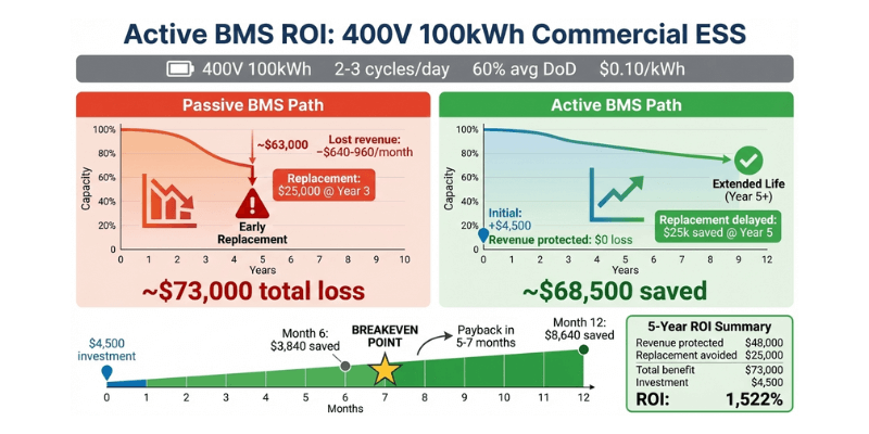
Case Study: Commercial Energy Storage
400V, 100kWh commercial energy storage system with 8% cell mismatch.
Lost capacity: 8kWh unavailable per charge cycle. System stores 92kWh instead of 100kWh. At $0.08-0.12/kWh commercial rates (US, 2024-2025), lost revenue ranges $640-960 per month. Regional pricing variance applies.
Accelerated degradation: Weakest cells hit voltage limits on every cycle. These cells age 30% faster than balanced cells. Pack replacement occurs at year 3 instead of year 5.
Cost analysis: Active BMS costs $4,500 more than passive for this system. Revenue recovery varies with cycling frequency. Under high-utilization commercial profiles (2-3 equivalent full cycles per day), monthly value recovery reaches $640-960 at $0.10/kWh pricing. Payback period: 5-7 months.
Note: This example assumes high-utilization cycling (multiple equivalent full cycles per day). EFC = equivalent full cycle (partial cycles summed to one full cycle). Recalculate ROI using your local commercial tariff and actual cycling profile. Energy pricing varies by region ($0.08-0.15/kWh).
Design Standards
Internal design rules at Holo Battery, revised yearly:
- Mandatory Active Balancing: Systems above 96V nominal use active charge redistribution. Products below 96V evaluate case-by-case.
- Minimum Balancing Current: Active balancers operate at minimum 5A for packs from 100-300Ah. 10A balancing required for packs above 300Ah.
- EMI Mitigation: According to CISPR 25 Class 5 limits, active balancing circuits include LC filters to prevent noise interference with CAN bus. Ferrite beads on balancer power lines. Shielded enclosures for balancer PCBs.
- Temperature Compensation: BMS firmware adjusts balance thresholds based on pack temperature. Tighter thresholds (5mV) at 25°C. Relaxed thresholds (20mV) below 0°C or above 45°C.
FAQ
How do you size the balancing current?
Follow these steps:
- Calculate 5-10% of pack capacity (200Ah pack = 10-20A requirement)
- Divide by cell count for per-cell requirement
- Add 2-3x margin for peak correction events
- Verify timing: C/10 rate allows 10-hour worst-case rebalancing, C/20 rate takes 20 hours
Is active balancing worth the cost for LFP batteries?
Yes for LFP. LFP voltage stability (3.20-3.30V across 60% SOC) makes passive balancing ineffective during mid-range operation. Active charge redistribution costs $3-5 per cell but extends lifetime by 500-1000 cycles.
ROI example: 16S pack costs $80 more for active balancing. On a $2000 battery with 1000-cycle extension, savings equal $0.50 per cycle. Payback occurs in 160 cycles (six months of daily cycling).
Does active balancing work during discharge?
Yes. Active balancing works during charge, discharge, and idle states. Discharge balancing prevents weak cells from limiting total pack output. This maintains full power capability throughout the discharge cycle.
Discharge balancing requires the BMS to detect which cells limit discharge and transfer energy to those cells. This requires fast voltage measurement and rapid response.