


Прототип вашего портативного концентратора кислорода прекрасно работает на рабочем столе.
Компрессор обеспечивает чистоту кислорода более 90%. Алгоритмы оптимизируют энергопотребление. Промышленный дизайн выглядит готовым к производству. Затем вы указываете аккумулятор, и все разваливается.
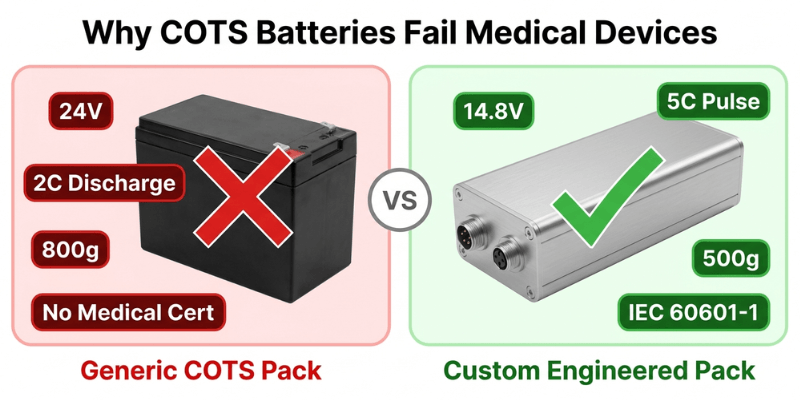
Готовые коммерческие модули (COTS) — это:
- На 300 г тяжелее, чем позволяет ваш весовой бюджет
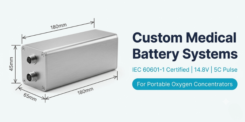
- Неправильное напряжение (24 В, когда нужно номинальное 14,8 В)
- Номинал непрерывного разряда 2C (для запуска двигателя необходим импульс 5C)
- Отсутствие сертификации IEC 60601-1 добавляет месяцы к вашему графику
Мы поставили сертифицированные аккумуляторные системы для 12+ портативных медицинских устройств. Вот что на самом деле работает.
Что на самом деле нужно инженерам медицинского оборудования
Готовые аккумуляторные модули выходят из строя портативных концентраторов кислорода по четырем причинам.
Неправильная архитектура напряжения
Вашему контроллеру двигателя необходим 14,8 В номинальный (литий-ионная конфигурация 3S4P или 3S5P). Пакеты COTS имеют напряжение 24 В или 7,4 В. Перепроектирование вашей силовой электроники с учетом доступных батарей — это обратная инженерия.
Недостаточная способность импульсного разряда
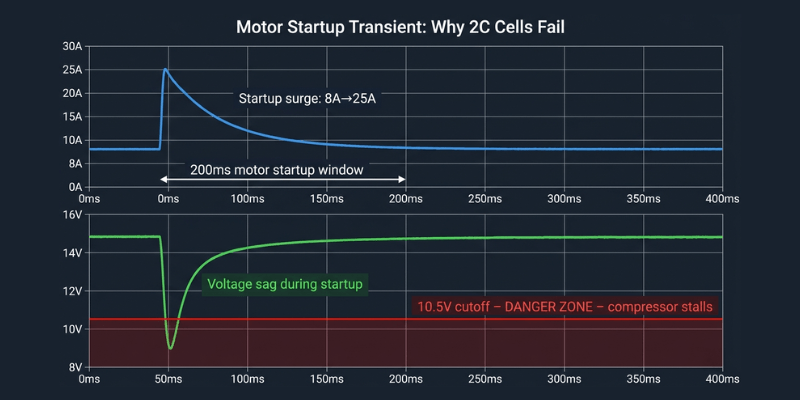
Ваш компрессор потребляет ток 8 А в устойчивом состоянии, но во время запуска двигателя он возрастает до 25 А на 200 мс. Большинство аккумуляторов COTS рассчитаны на непрерывный разряд 2C. Этот рейтинг подходит для постоянных нагрузок, но губителен для переходных процессов при запуске двигателя.
Когда напряжение падает ниже минимального порога контроллера в течение этого импульса 200 мс, ваш компрессор останавливается. Подача кислорода прекращается. Для медицинского устройства это потенциально фатальный режим отказа.
Пробелы в сертификации, которые задерживают запуск
Вам нужен IEC 62133-2 (безопасность ячеек), ООН38.3 (транспортировка) и интеграция в сертификацию вашего устройства по стандарту IEC 60601-1. Поставщики COTS предоставляют первые два. Третье становится вашей проблемой. К сожалению, это реальность, о которой большинство команд узнают слишком поздно.
Ограничения форм-фактора
Полость вашего промышленного образца составляет 180×65×45 мм. Пакеты COTS имеют стандартные размеры. “Достаточно близко” означает изменение конструкции вашего корпуса или увеличение объема на 15%.
Мы проектируем согласно вашим требованиям. Не вокруг того, что есть в продаже.
Проверка реальности плотности энергии
Зайдите к любому поставщику аккумуляторов, и они назовут вам впечатляющие цифры.
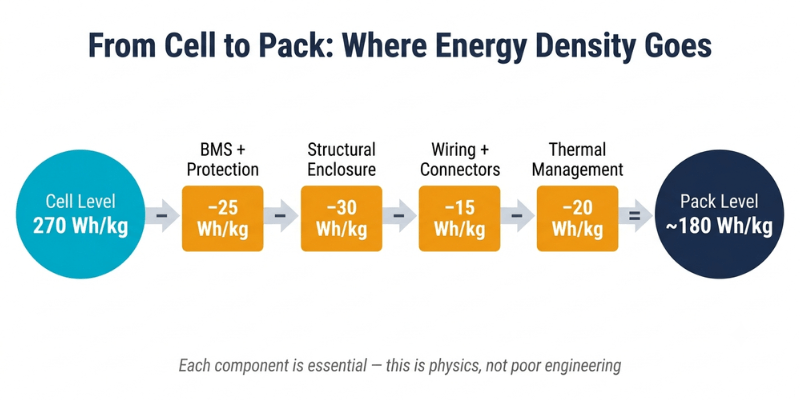
“Наши элементы вырабатывают 270 Втч/кг.”
Истинный. Однако это клеточный уровень. Вы не отправляете голые литиевые элементы в медицинском устройстве.
Что добавляется к голым клеткам
- Система управления аккумуляторами – контролирует напряжение элементов, управляет зарядом/разрядом, выполняет защитные отключения
- Защитная схема – защита от перегрузки по току, защита от короткого замыкания, тепловой контроль
- Структурный корпус – должен выдерживать падение на бетон с высоты 1 метра согласно IEC 60601-1
- Соединения и проводка – рассчитан на требования к току и температуре медицинского устройства
- Управление температурным режимом – поддерживает температуру клеток ниже 45°C во время работы в непрерывном потоке
- Защитное отключение – резервная защита в случае сбоя BMS
Вся эта необходимая инфраструктура снижает плотность энергии почти вдвое. В технических характеристиках элементы Premium 21700 могут достигать 270 Втч/кг. Готовый медицинский аккумуляторный блок обеспечивает мощность от 150 до 180 Втч/кг при производстве.
Это не плохая инженерия. Это физика и нормативная реальность.
Что это значит для вашего продукта
Реалистичная упаковка 160 Втч/кг, обеспечивающая 80 Втч, обеспечивает:
- 4 часа работы в режиме импульсной дозы
- 2 часа работы в непрерывном потоке
- 500 г аккумулятор в сборе
- Общий вес устройства 2,8 кг.
Ваша маркетинговая команда хочет заявить “6 часов работы.” Ваша команда инженеров знает, что для этого требуется более тяжелая упаковка, которая превышает порог портативности, менее эффективный компрессор или только режим импульсной дозы. Выберите один.
Мы помогаем вам ориентироваться в этих компромиссах с помощью реальных цифр.
Почему ваш компрессорный двигатель разрушает плохие батареи
Двигатели кислородных компрессоров агрессивны к аккумуляторным блокам, что не проявляется при испытаниях в установившемся режиме.
Проблема всплеска стартапов
Двигателям компрессоров необходим высокий крутящий момент для преодоления статического трения при первом такте. Этот первоначальный всплеск потребляет в три-пять раз больше нормального рабочего тока в течение 100-300 миллисекунд.
Дешевые элементы с высоким внутренним сопротивлением постоянному току образовывают кратеры во время этого скачка напряжения, что приводит к резкому падению напряжения. Минимальный порог контроллера двигателя обычно составляет 10,5 В для номинальной системы 14,8 В. Если напряжение падает ниже этого уровня, компрессор останавливается и подача кислорода прекращается.
Температура все ухудшает
Внутреннее сопротивление элемента резко меняется в зависимости от температуры и состояния заряда:
- При 0°C: сопротивление может утроиться по сравнению с 25°C.
- При 20 % заряда: сопротивление увеличивается примерно вдвое по сравнению с 80 % заряда.
- Комбинированный эффект: холодный, почти разряженный аккумулятор может иметь в 6 раз большее сопротивление, чем теплый, полностью заряженный.
Стендовые испытания при комнатной температуре со свежими элементами скрывают режим отказа, который приводит к гибели устройств в полевых условиях. При эксплуатации в мороз, когда осталось всего 30% заряда и в трех километрах от дома ведет себя как совсем другой аккумулятор.
Критерии выбора ячеек, которые действительно имеют значение
Мы указываем ячейки, рассчитанные на:
- 3C непрерывный разряд – для расширенной работы в непрерывном потоке
- Импульсный режим 5C – для запуска двигателя без провалов напряжения
- Стабильная работа при температуре от 0°C до 40°C. – полный рабочий диапазон
- Стабильный результат за счет деградации – по-прежнему соответствует техническим характеристикам при мощности 80% после 500 циклов
Мы тестируем аккумуляторы под вашим фактическим профилем нагрузки при экстремальных температурах и различных состояниях заряженности. Не только непрерывная разрядка при комнатной температуре.
Скрытая инженерная задача: легкий и прочный
В промышленных аккумуляторных блоках используются толстые пластиковые и стальные кронштейны, потому что лишние 200 грамм никого не волнуют. Медицинские концентраторы кислорода отчаянно заботятся о каждом грамме, даже несмотря на обязательные испытания, которых никогда не проходят промышленные упаковки:
- Испытание на падение – 1 метр на бетон, 6 ориентаций, отсутствие разрывов и нарушений электробезопасности
- Тест на вибрацию – имитация транспортировки и ежедневного использования, все соединения не повреждены
- Термальный велоспорт – от −40°C до +60°C, корпус сохраняет структурную целостность
- Краш-тест – симулированный пользователь сидит на устройстве, ячейки не повреждены
Как мы создаем легкие и безопасные корпуса
Анализ методом конечных элементов определяет точные точки напряжения. Мы моделируем ударные и вибрационные нагрузки при падении в САПР, а затем добавляем армирование только там, где этого требует физика, вместо того, чтобы использовать стены одинаковой толщины, тратя материал. Оптимизированные таким образом корпуса из поликарбоната экономят от 15 до 25 % массы по сравнению со стандартными промышленными конструкциями. На упаковке 500 г это экономия от 75 до 125 г, что обеспечивает достаточный запас мощности для добавления 15 Втч емкости при том же весовом бюджете.
Стратегический выбор материала:
- Поликарбонат для зон повышенного воздействия – На 30 % легче, чем ABS, и обладает лучшей ударопрочностью.
- Алюминиевые теплораспределители только в тех случаях, когда термическое моделирование позволяет выявить горячие точки.
- Полиимидные пленки для электроизоляции. – тоньше и легче традиционных полимеров
Миф об использовании только клея
Чистые клеевые соединения разрушаются при ударных нагрузках, поскольку термоциклирование ухудшает прочность соединения. Мы видели, как пакеты проходят первоначальное испытание на падение, а затем выходят из строя после 200 термических циклов. – 18 месяцев эксплуатации в полевых условиях, развернуто 5000 единиц.
Наш подход сочетает в себе конструкционный клей с элементами механического крепления, залитыми непосредственно в корпус. Клей выдерживает нормальные нагрузки и вибрацию. Механические характеристики предотвращают катастрофический выход из строя по мере старения клея.
Конструкция для замены на месте
Советовать пациенту выбросить концентратор стоимостью 3000 фунтов стерлингов, потому что батарея разрядилась через 18 месяцев, — это одновременно расточительно и коммерчески недальновидно. Ваши конкуренты предлагают сменные батареи.
Мы разрабатываем пакеты с документированными процедурами замены, разъемами, рассчитанными на более чем 50 циклов подключения, интерфейсами с ключами, предотвращающими неправильную установку, и диагностикой BMS, которая сообщает о состоянии ячеек до того, как произойдет катастрофический сбой.
Удобство обслуживания должно быть спроектировано на основе первой модели САПР. Его невозможно модернизировать.
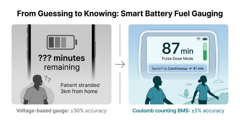
Учет топлива: почему пациентам нужны минуты, а не столбцы
Посмотрите, что на самом деле видят пациенты с хорошо продуманной BMS:
На дисплее отображается “В импульсном режиме осталось 87 минут.” Они переходят на непрерывный поток. Он обновляется до “Осталась 41 минута.” Они точно знают, что делать с оставшимся зарядом, и выходят из дома.
Теперь посмотрим, что они видят при измерении напряжения: три полоски, которые почти ничего не значат в середине 60% разряда, когда кривая напряжения лития почти плоская. Пациент, который думает, что у него осталось 45 минут, а на самом деле осталось 15, попадает в затруднительное положение. Ваше устройство обвиняют.
Почему датчики напряжения выходят из строя
Напряжение литиевого элемента почти ничего не говорит вам об оставшейся емкости при уровне заряда от 80% до 30%. Кривая плоская. В реальных условиях точность снижается до ±25-30%. Эта погрешность представляет собой разницу между возвращением домой и возвращением домой.
Что предоставляют передовые системы BMS
Современная прошивка BMS использует подсчет кулонов в сочетании с отслеживанием импеданса, измеряя фактический поток заряда, а не делая вывод о емкости по напряжению. В системе учитывается:
- Емкость снижается по мере старения аккумулятора
- Разница в потребляемой мощности между импульсной дозой и непрерывным потоком
- Влияние температуры на доступную мощность
- Недавняя история загрузок
Это обеспечивает точность ±5% в реальных условиях эксплуатации.
Требования к интеграции
Для этого с самого начала требуется надлежащая связь между BMS и главным системным контроллером:
- Протоколы SMBus или I2C для обмена данными в реальном времени.
- Обновление переключения режимов, поэтому BMS пересчитывает, когда компрессор меняет режимы.
- Обмен данными о температуре между системным контроллером и BMS
- Отчет о состоянии сбоя до того, как деградировавшие клетки станут клинической проблемой.
Планируйте эту интеграцию с первого дня. Его нельзя закрепить во время окончательного тестирования.
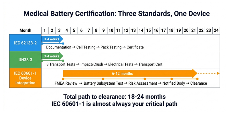
Путь сертификации: реалистичные сроки и стоимость
Всегда кто-то спрашивает: “Разве мы не можем немного изменить существующий сертифицированный пакет?”
Нет. Любая модификация сертифицированного медицинского компонента требует полной ресертификации. Вы можете сэкономить 6 недель на разработке и потерять 8 месяцев на ожидании результатов повторного тестирования.
МЭК 62133-2: Безопасность элементов и батарей.
Проверяется внешнее короткое замыкание, термическое воздействие, механический удар, вибрация и защита от перезаряда. Ваш поставщик ячеек сертифицирует отдельные ячейки. Вам по-прежнему необходимо отдельное тестирование на уровне упаковки, поскольку ваша BMS, корпус и межсоединения меняют профиль безопасности.
Требуемые образцы: от 3 до 4 упаковок | Стоимость: 1500–2000 фунтов стерлингов | Срок: от 3 до 4 недель.
UN38.3: Транспортная безопасность
Восемь обязательных испытаний, имитирующих воздушный транспорт: воздействие высоты, термоциклирование, вибрация, механический удар, короткое замыкание, раздавливание, перезаряд и принудительный разряд. Обязательно, если пациенты путешествуют самолетом, и они будут это делать.
Требуемые образцы: от 3 до 4 упаковок | Стоимость: 700–900 фунтов стерлингов | Срок: от 3 до 4 недель.
МЭК 60601-1: Интеграция медицинской электробезопасности
Ваша батарея должна пройти полную сертификацию устройства. Испытательная лаборатория оценивает влияние вентиляции ячеек на класс IP корпуса, опасность ожога пользователя при перегреве, опасность поражения электрическим током и влияние отказа BMS на подачу кислорода. Уполномоченный орган проверяет ваш FMEA на предмет каждого режима отказа батареи.
Стоимость: 2000–3000 фунтов стерлингов за аккумуляторную подсистему | Сроки: от 4 до 8 недель для тестирования отдельных аккумуляторов | Примечание. Это включается в полную сертификацию вашего устройства, которая обычно длится от 6 до 12 месяцев.
ISO 13485: Система менеджмента качества.
Это не тестирование продукта; это требование процесса. Каждый компонент требует документированной прослеживаемости: квалификация производителя элементов, процедуры входного контроля, проверка процесса сборки и контроль изменений.
Стоимость: Внутренняя (обычно от 0,5 до 1,0 штатного инженера по качеству) | Сроки: Текущий
Реальная стоимость замены сотовой связи
Клиент заменил одну модель ячейки того же производителя, той же емкости и “улучшенный” статус. Уполномоченный орган потребовал провести полное повторное тестирование по стандарту IEC 62133-2, поскольку в паспорте химических веществ были обнаружены незначительные различия.
Результат: 4 недели лабораторного времени. 1800 фунтов стерлингов в качестве гонорара. Задержка один месяц. Зафиксируйте спецификацию ячейки перед началом сертификации.
Полный реалистичный график
Как мы снижаем риск сертификации
Мы изучили IEC 60601-1 с четырьмя различными уполномоченными органами на рынках ЕС и США. Мы знаем, какие протоколы испытаний применяются к аккумуляторным подсистемам и какая документация запрашивается во время проверки.
Мы создаем эту документацию с первого дня: полный FMEA для каждого режима отказа батареи, отчеты об испытаниях, показывающие реакцию BMS на условия неисправности, анализ снижения температурного неконтроля и проверку программного обеспечения для прошивки BMS.
Это не ускоряет сертификацию. Это делает его предсказуемым и позволяет избежать риска обнаружения недостающих требований, когда вы уже прошли 80 % проверки.
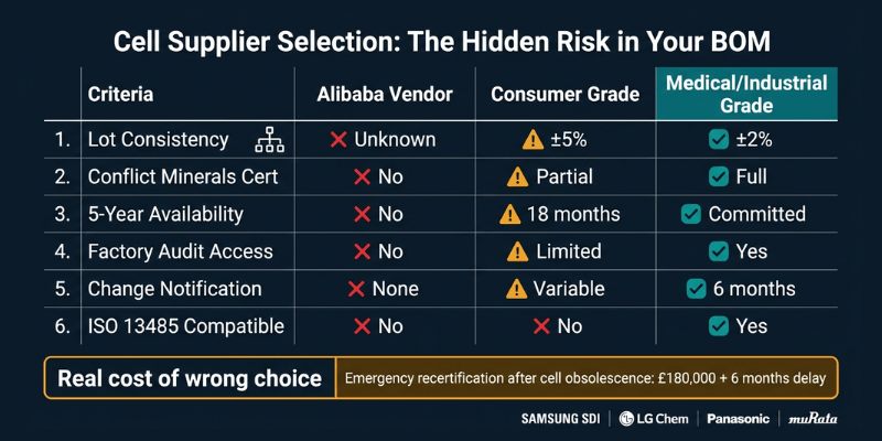
Реальность цепочки поставок: почему выбор ячеек выходит за рамки спецификаций
Ваш отдел закупок спросит: “Почему мы не можем использовать более дешевые клетки?”
Вот чего они не видят.
Доступность ячеек в течение более 5 лет срока службы продукта
Вы разрабатываете устройство со сроком службы от 5 до 7 лет. Элементы бытовой электроники снимаются с производства каждые 18 месяцев, поскольку производители гонятся за циклами проектирования смартфонов.
Мы отбираем клетки от производителей, имеющих линейку медицинской и промышленной продукции. Эти поставщики предлагают долгосрочные обязательства по обеспечению доступности, поскольку этого требуют их клиенты из автомобильной и медицинской промышленности.
Чего на самом деле стоит плохой выбор ячеек: 18650 потребительского класса, используемый в портативном аппарате искусственной вентиляции легких, устарел через 14 месяцев после запуска продукта. У производителя было 8000 единиц в эксплуатации без подходящей замены. Экстренный редизайн и повторная сертификация обошлись в 180 000 фунтов стерлингов и отложили выпуск следующего продукта на 6 месяцев.
Согласованность между партиями
Потребительские элементы имеют разброс мощности ±5% между производственными партиями. Клетки медицинского класса содержат ±2% с полной отслеживаемостью партии. Каждая ячейка имеет код даты и номер партии, поэтому, если возникнет проблема с качеством, вы сможете отследить ее до конкретной производственной партии.
Это важно, когда вы утверждаете “4 часа работы” врачам, которые принимают решения о лечении на основе этого числа.
Квалификация поставщика по стандарту ISO 13485
Ваша система качества требует проведения аудита поставщиков. Может ли ваш поставщик сотовой связи предоставить:
- Декларации о конфликтных минералах (требуются для продажи медицинского оборудования в ЕС и США)
- Документация о соответствии RoHS и REACH
- Доступ к заводскому аудиту для вашей команды качества
- Документированное уведомление об изменении – Предварительное уведомление за 6 месяцев до любого изменения процесса
Производители первого уровня, такие как Samsung SDI, LG Chem, Panasonic, Murata, предоставляют все это. Продавцы Alibaba ничего из этого не предоставляют.
Стратегия второго источника
Во время COVID срок поставки аккумуляторов увеличился с 8 до 26 недель. Компании с разработкой из одного источника прекратили производство.
Мы аттестуем элементы вторичного происхождения на этапе первоначального проектирования и поддерживаем эту документацию на протяжении всего срока службы продукта. Когда ваш основной поставщик переходит к распределению, вы переключаетесь на квалифицированного заместителя. Это устраняет необходимость экстренного изменения конструкции или повторной сертификации.
Это особенно важно, когда вы масштабируете объем производства со 100 до 1000 единиц в месяц, а ваш основной поставщик не успевает за ним.
Управление температурным режимом и срок службы батареи
Почему рабочая температура определяет экономику продукта
Большинство качественных литиевых элементов выдерживают длительную эксплуатацию при температуре 60°C. Но срок службы резко ухудшается при температуре выше 45°C:
| Рабочая температура | Циклы до 80% емкости |
| 45°С | 500 циклов |
| 35°С | 1000+ циклов |
| 25°С | 1500+ циклов |
Для устройства, используемого ежедневно, это разница между 18 и 48 месяцами автономной работы. В этом также заключается разница между управляемыми затратами на обслуживание и проблемой экономики продукта.
Мы стремимся к тому, чтобы максимальная температура упаковки была ниже 50°C во время непрерывной работы при температуре окружающей среды 25°C. Это обеспечивает запас на более высокие температуры окружающей среды летом, ухудшение тепловых характеристик по мере старения клея и накопление пыли на вентиляционных путях, снижающее поток воздуха.
Подход к тепловому расчету
Ячейки внутри блока нагреваются сильнее, чем ячейки по периметру. Элементы рядом с компонентами BMS получают дополнительное тепло от электроники. Тепловое моделирование во время проектирования выявляет эти горячие точки и определяет стратегическое размещение ячеек и распространение тепла.
В большинстве портативных кислородных концентраторов используется пассивное охлаждение, основанное на теплопроводности к корпусу с последующей естественной конвекцией. Активное охлаждение увеличивает массу от 20 до 40 г, паразитное потребление от 0,5 до 1,0 Вт, еще один режим отказа и шум, мешающий использованию в ночное время.
Мы разрабатываем пассивное охлаждение, подходящее для типичного использования, при поддержке системы мониторинга температуры BMS, которая предупреждает пациентов, когда температура упаковки превышает безопасные пределы, снижает скорость компрессора, если температура продолжает расти, и регистрирует тепловые данные для анализа неисправностей на месте.
Продление практического срока службы
Создайте упаковку, превышающую минимальные требования. Если вам нужно 80 Втч для работы в течение 4 часов, создайте аккумулятор на 120 Втч. Обычное использование разряжает только 65% вместо 100%, что увеличивает срок службы до 1000–1500 циклов. Увеличение веса и стоимости окупается за счет сокращения необходимости замены аккумуляторов в полевых условиях.
Ограничьте тарифы сборов до 0,5C. Медицинские приборы заряжаются в течение ночи. Нет никакой клинической пользы от быстрой зарядки в течение 1 часа. Более медленная зарядка уменьшает количество литиевого покрытия и значительно продлевает срок службы.
Встраивайте замену в дизайн продукта с первого дня. Пациентам следует ожидать замены батареи через 24–36 месяцев ежедневного использования; это честный подход. Принуждение их к замене концентратора стоимостью 3000 фунтов стерлингов из-за разряда батареи создает конкурентную уязвимость и наносит ущерб вашему бренду.
Что происходит, когда вы связываетесь с нами
Нам нужны ваши реальные требования, а не амбициозные цели.
Что отправить
- Электрические характеристики компрессора – пусковой ток, установившееся потребление в зависимости от режима, диапазон напряжения, пиковая длительность импульса
- Физические ограничения – максимальные габариты, весовой диапазон, расположение разъема
- Операционная среда – диапазон температур, высота над уровнем моря, рабочий цикл
- Целевое время выполнения – часов на одну зарядку в каждом режиме работы
- Объемы производства – влияет на принятие инвестиционных решений
- Сроки и путь сертификации – FDA 510(k), MDR ЕС, другие рынки
Сначала оценка осуществимости. Некоторые комбинации производительности, размера и веса не могут быть достигнуты с помощью современной литиевой технологии. Если ваши требования достижимы, мы наметим доступные компромиссы: добавьте 50 г и получите 1 час работы, уменьшите пиковый ток до 4C и сэкономьте 8 фунтов стерлингов за упаковку, примите минимум 3,5 часа вместо гарантированных 4,0 часа. Реальные опционы с реальными числами.
Эскизный проект с техническим обоснованием. Обоснование выбора элемента, варианты архитектуры корпуса, требования к функциям BMS, оценки производительности при экстремальных температурах и окончании срока службы, примерная стоимость при ваших объемах производства. Две недели.
Создайте прототип и проверьте его перед сертификацией. Мы создаем прототипы блоков и тестируем их под вашим реальным профилем нагрузки: переходные процессы при запуске двигателя при различных состояниях заряда, непрерывный поток до температурного устойчивого состояния, работа с импульсной дозой, соответствующая вашему клиническому рабочему циклу, экстремальные температуры при 0 ° C и 40 ° C, а также моделирование производительности в конце срока службы.
Потратить 50 000 фунтов стерлингов на прототипы, обнаруживающие конструктивные недостатки, — это дешево. Потратить 300 000 фунтов стерлингов на сертификационные испытания, которые провалились из-за того, что вы пропустили проверку прототипа, — это дорого.
Сертификационная поддержка с реалистичными сроками. Мы предоставляем планы испытаний, соответствующие стандартам IEC 62133-2 и IEC 60601-1, документацию FMEA для проверки уполномоченным органом, документацию файла истории проектирования для подачи в регулирующие органы, а также квалификационную документацию поставщика для вашего аудита по ISO 13485.
Чего мы не делаем
Мы не обещаем волшебных решений. Плотность энергии батареи увеличивается на 3–5% в год. Никаких 50%-ных прорывов не произойдет.
Мы не игнорируем требования регуляторов. “С сертификацией разберемся позже” вот как проекты терпят неудачу на финишной прямой после 18 месяцев разработки.
Мы не притворяемся, что разработка занимает 3 месяца, тогда как на нее уходит от 18 до 24 лет. Сроки разработки медицинского устройства длительны. Сжатие их на бумаге никому не поможет.
Часто задаваемые вопросы
Сколько времени на самом деле занимает разработка индивидуальных медицинских батарей?
От 18 до 24 месяцев от первоначальных требований до получения разрешения регулирующих органов: проектирование (3–4 месяца), создание прототипа (2–3 месяца), проверка конструкции (2–3 месяца), сертификационные испытания компонентов (3–4 месяца), интеграционное тестирование устройств (6–12 месяцев), проверка регулирующими органами (6–12 месяцев). Фазы перекрываются там, где это возможно. Компании, обещающие более быстрые сроки, пропускают этапы проверки или не понимают требований к медицинскому оборудованию.
Что произойдет, если наш поставщик ячеек прекратит выпуск указанной ячейки?
Мы аттестуем элементы вторичного происхождения на этапе первоначального проектирования и ведем эту документацию. Когда основные элементы устаревают, вы переключаетесь на квалифицированную альтернативу без экстренного изменения конструкции или повторной сертификации. Это стоит дороже. Это стоит гораздо меньше, чем альтернатива.
Могут ли пациенты заменить батареи самостоятельно или для этого требуется сервисный центр?
Любой подход работает. Для конструкций, заменяемых пациентом, необходимы надежные разъемы и четкие инструкции. Замена сервисного центра обеспечивает более сложную интеграцию. Мы успешно разработали оба варианта. Правильный выбор зависит от вашей модели обслуживания и структуры затрат, а не от того, что технически проще построить.