Kľúčové informácie:
- Lítium-iónové batérie sú komplexné zostavy, ktoré zahŕňajú bunky, systém na správu batérií (BMS), pasívne komponenty, kryt a systém tepelného riadenia. Poháňajú rozsiahlu škálu aplikácií, od spotrebnej elektroniky po elektrické vozidlá a vyžadujú starostlivé inžinierstvo, aby sa zaistila bezpečnosť, efektívnosť a spoľahlivosť.
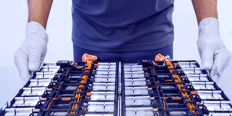
A lítium-iónová batéria Pack je zostavenie lítium-iónových buniek, systém na správu batérií a rôzne podporné komponenty všetky obsiahnuté v kryte. Poskytuje nabíjateľné skladovanie energie a energiu pre nespočetnú spotrebnú elektroniku, elektrické vozidlá, skladovacie systémy siete a ďalšie priemyselné aplikácie.
Zatiaľ čo lítium-iónové bunky poskytujú základnú elektrickú kapacitu, ostatné integrované komponenty sú rovnako kritické pri umožňovaní bezpečnej, efektívnej a spoľahlivej funkčnosti. V tejto príručke sa podrobnejšie pozrieme na technické aspekty každého základného litium-iónového komponentu batérií.
Prehľad kľúčových komponentov
Lítium-iónové batérie obsahujú nasledujúce hlavné komponenty:
- Lítium-iónové bunky – Základná elektrochemická jednotka poskytujúca elektrickú úložnú kapacitu. Viaceré bunky sa kombinujú, aby sa dosiahlo požadované napätie a kapacita.
- Systém správy batérie (BMS) – „Mozog“ monitorujúce bunkové podmienky a kontrola bezpečnosti a výkonu.
- Pasívne komponenty – Poskytnite štruktúru, prepojenie, izoláciu a chladenie.
- Ohrada – Domy a chránia všetky vnútorné komponenty.
- Systém tepelného riadenia – Udržiava optimálne teploty buniek pre prevádzku.
- Dodatočná elektronika – Pridané funkcie, ktoré zvyšujú funkčnosť a integráciu.
Ďalej preskúmame každú z týchto komponentov v väčších technických detailoch.
Lítium-iónové bunky: elektrochemický zdroj energie
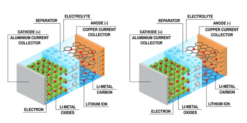
Lítium-iónové bunky využívajú lítium-iónovú interkalačnú chémiu na reverzibilné ukladanie elektrickej energie elektrochemicky. V bunke sa k dispozícii pozitívne nabité lítium -ióny medzi grafitovou anódou a katódou na oxid kovu, keď sa bunka nabíja a vypúšťa. Organický elektrolyt umožňuje transport iónov, zatiaľ čo pórovitý oddeľovač zabraňuje elektrickým kontaktom medzi elektródami.

Bunky sa dodávajú v rôznych štandardných veľkostiach a formálnych faktoroch:
- Valcové (napr. 18650, 21700, 4680): špirálovité vrstvy elektródy/separátora vo valcovom kovovom plechovke. Vyššia hustota energie, ale nižšia hustota energie v porovnaní s bunkami vrecka. Bežné formáty:
- 18650 – Priemer 18 mm, výška 65 mm, typická kapacita 1,5–3 AH
- 21700 – Priemer 21 mm, výška 70 mm, až do 5ach kapacity
- 4680 – Priemer 46 mm, výška 80 mm, kapacita 10-50AH
- Hranolový – Striedateľná katóda, anóda a odlučovacie vrstvy sa naskladali a zložili do prizmatického hliníkového krytu. Maximalizuje objemovú hustotu energie, ale nižšiu hustotu energie. Bežné formáty:
- Kapacity 10AH a 30AH pri nízkych radoch C
- Rozmery okolo 100 x 200 x 10 mm
- Vrecko – Elektródy a oddeľovač utesnené v kovovom plastovom laminátovom vrecku. Tiež známe ako polymérne bunky. Flexibilné a ľahké. Nákladovo efektívne, ale menej odolné puzdro. Typické hodnotenie kapacity od 1 do 300 HA.
Lítium-iónové bunky tiež využívajú rôzne katódové chemikácie, ovplyvňujúc napätie, kapacitu a bezpečnosť:
- Oxid kobaltu lítium (LCO) - 3,6 V nominálne napätie, vysoká hustota energie, ale bezpečnostné obavy pri zvýšených teplotách
- Oxid mangánu lítium (LMO) - 3,7 V, bezpečnejšia a dlhšia životnosť cyklu, ale nižšia kapacita
- Fosfát lítium (LFP) – 3,2V, veľmi bezpečné a odolné, ale nižšia hustota energie
- Oxid kobaltu mangánu lítium (NMC) – 3,6/3,7 V, vysoká kapacita a hustota energie, ale zložitejšia výroba
- Hliník lítium niklu (NCA) - 3,6 V, vysoká kapacita a hustota energie, ale kratšia výdrž batérie
Pri výbere buniek inžinieri vyhodnotia parametre, ako je nominálne napätie, kapacita, rýchlosť C, životnosť cyklu, formálny faktor, bezpečnosť, náklady a dostupnosť, aby sa splnili požiadavky na aplikáciu. Vysoké kapacity chemikácie NMC a NCA sa stali spoločnými pre vysoko výkonné aplikácie.
Systém správy batérie (BMS)
The riadenie batérie slúži ako „mozog“, ktorý riadi celkovú prevádzku batérie. BMS monitoruje bunkové podmienky, riadi bezpečnostné mechanizmy, vyvažuje bunky a poskytuje komunikačné rozhrania. Zložitosť BMS závisí od veľkosti a funkčnosti balenia. Malé spotrebiteľské BMS môžu zahŕňať iba:
- Monitorovanie napätia a teploty buniek
- Predchádzanie nadmernému nabíjaniu a nadmernému vybitiu
- Vyváženie buniek
Zatiaľ čo BMS BACK BACK EV poskytuje rozsiahle funkcie:
- Monitorovanie vysokej presnosti napätia (± 15 mV), prúdu (± 1-2%) a teploty (± 1 ° C) pre každú bunku
- Aktívne vyvažovanie buniek prostredníctvom posunutia alebo viacväťových transformátorov
- Ovládanie stykuče a poistky pre elektrickú izoláciu
- Komplexné algoritmy stavu náboja a odhadu zdravia
- Tepelné riadenie prostredníctvom riadenia chladiaceho systému
- Detekcia vysokej rýchlosti kritického poruchy – Otvorený/skrat, nadmerná časť
- Stovky vstupov senzora a riadiacich výstupov
- Komunikačné rozhrania vozidla – Can, Lin, Flexray, Automotive Ethernet
- Zabezpečená autentifikácia, ochrana proti neoprávnenému manipulácii, aktualizácie firmvéru cez vzduch
- Podrobné protokolovanie údajov pre diagnostiku a počítanie cyklu

zdroj: Výskumy
Hardvér BMS sa zvyčajne skladá z ICS, ADC, mikrokontrolérov a obvodov riadenia napájania namontovaných na doske s tlačenými obvodmi. Pre bezpečnosť a spoľahlivosť sú rozhodujúce pre bezpečnosť a spoľahlivosť vysoké napätie a robustné spojenia.
Pasívne komponenty
Okrem buniek a BMS obsahujú lítium-iónové batérie aj rôzne pasívne komponenty:
- Bus tyče - poskytujte nízke odporové spojenia medzi bunkami a terminálmi. Vyžaduje sa vysoká súčasná kapacita – Až 1000a v balíkoch EV. Meď alebo hliníkové autobusové tyče môžu byť holé, nanesené alebo potiahnuté. Dizajn baru z autobusu minimalizuje indukčnosť pri zachovaní izolácie.
- Materiál na tepelné rozhranie – Používa sa medzi bunkami a stenami krytu alebo chladiacimi kanálmi. Silikónové elastoméry, tepelne vodivé pásky a podložky na vyplňovanie medzery maximalizujú prenos tepla. Materiály na zmenu fázy ponúkajú vysokú tepelnú kapacitu.
- Lepidlá a pásky - poskytujte elektrickú izoláciu a odpor vibrácií. Materiály zahŕňajú polyuretán, akrylové lepidlá a silikón. Obojstranné tepelne vodivé pásky sú bežné. Prísne hodnotenie horľavosti UL94 V-0.
- Poistky a stykače - chráňte pred nadprúdovými chybami. Umožnite tiež bezpečnú elektrickú izoláciu. Vyžaduje sa vysoké hodnotenie napätia a prúdu. Poistky môžu byť integrované do BMS. Predbežné obvody obmedzujú prúdový prúd.
- Bunkové prepojenia - spájajte bunkové terminály v sérii. Musí zvládnuť vysokú hustotu prúdu. Používa sa ultrazvukové, laserové a odporové zváranie.
Starostlivo výber týchto pasívnych komponentov zaisťuje elektrické, tepelné a mechanické integritu batérie v náročných podmienkach.
Batéria
Kryt alebo kryt batérie poskytuje:
- Ochrana – Bunky chránené pred mechanickým zneužívaním, nárazom, prachom, tekutinou. Umožňuje iba správne elektrické pripojenia. Poskytuje hodnotenie IP založené na aplikácii.
- Štrukturálna podpora – Poskytuje požadovanú tuhosť na stohovanie buniek a montáž. Rozhrania s aplikačným rámom a zátvorkami.
- Chladiace kanály – Umožňuje prietok vzduchu alebo cirkuláciu chladiacej kvapaliny kvapaliny naprieč bunkami a BMS. Môže obsahovať integrované chladiace plutvy.
- Izolácia – Elektricky izoluje komponenty vysokého napätia, ako sú bary a terminály zbernice.
- Environmentálne tesnenie - zabraňuje vlhkosti. Potrebné pre lítium-iónové chemické prostriedky.
Medzi bežné krytiny patria kovy, ako je hliník pre vynikajúce tepelné vlastnosti, a inžinierske plastové zmesi pre ľahšiu hmotnosť a odolnosť proti korózii. Kovové a uhlíkové vlákna posilnené plasty poskytujú štrukturálnu tuhosť a tienenie.
Kryty sú často vybavené odnímateľnými prístupovými panelmi pre servisné a modulárne konštrukcie balení pre flexibilitu inštalácie. Štrukturálne lepidlá, tesnenia a izolačné membrány udržiavajú komponenty bezpečne namontované a izolované.

Systém tepelného riadenia
Udržiavanie správnej teploty buniek je rozhodujúce pre bezpečný a optimálny výkon lítium-iónových batérií. Aj keď lítium-iónové bunky fungujú dobre okolo 15-35 ° C, prevádzka mimo tohto rozsahu znižuje výkon a životnosť:
- Kapacita výtoku klesá pod zmrazenie. Zvyšuje sa vnútorný odpor.
- Nad ~ 50 ° C sa vybledne a starnutie rýchlej kapacity.
- Nad ~ 60 ° C Riziko tepelného utečenia eskaluje.
Teda systém tepelného hospodárenia musí počas prevádzky ochladiť bunky a zahriať ich, keď je statický v chladných okolitých podmienkach. Typické metódy chladenia zahŕňajú:
- Pasívny vzduch – Chladenie prostredníctvom plutiev a kanálov. Používa sa v menších baleniach s nižším tepelným výstupom.
- Nútený vzduch – Axiálne alebo odstredivé ventilátory zlepšujú rýchlosť prúdenia vzduchu a prenos tepla. Potrubia optimalizujú distribúciu toku.
- Chladenie tekutiny – Bundy, dosky alebo mikrokanálové cirkulácie zmesou vody/glykolu alebo dielektrickej tekutiny. Veľmi efektívne pre vysoko výkonné balíčky >5 kW.
- Materiály na zmenu fázy – Voskové materiály absorbujúce teplo, keď sa topia. Používa sa v krytoch alebo ako tepelné vankúšiky.
- Termoelektrické - Peltierské zariadenia generujú teplotný rozdiel pri napájaní. Kompaktné chladenie v tuhom stave.
Zahrievanie je tiež rozhodujúce pre prevádzku chladiarenského podnebia. Metódy vykurovania zahŕňajú:
- Elektrické ohrievače – Odporné ohrievače pripevnené k krytu balenia.
- Tepelné čerpadlá – Reverzné termoelektrické zariadenia alebo kompaktné slučky chladiva.
- Plytvanie – Zachytenie odporových strát pri nabíjaní a vybíjaní.
BMS monitoruje bunkové teploty a riadi ochladenie alebo zahrievanie podľa toho na základe patentovaných kontrolných algoritmov. Veľké batérie sa môžu rozdeliť do tepelných zón s nezávislou reguláciou teploty.
Ďalšie komponenty
V závislosti od požiadaviek na náklady, tvarový faktor a aplikácie môžu balenie lítium-iónových batérií obsahovať ďalšie komponenty:
- Okruh prebudenia – Pri začatí nabíjania/výboja prebudia spiace BMS. Zlepšuje súčasný pohotovostný režim.
- Vyváženie buniek obvody – Aktívne vyváženie poskytuje viac presnosti ako samotné pasívne vyváženie. Vyžaduje pridanú zložitosť.
- Obvod – Pri pripojení balíček obmedzuje prúd. Používa rezistory alebo aktívne prepínanie. Chráni BMS a stykače.
- Nabíjačka – Na palube elektronika nabíjania na nabíjanie pre rýchle nabíjanie DC. Odstraňuje potrebu externej nabíjačky.
- Komunikácia – Okrem základného rozhrania BMS môžu balíčky obsahovať bezdrôtové moduly alebo komunikáciu napájacieho vedenia (PLC) pre diaľkové ovládanie a diagnostiku.
- Ohrievač – Poskytnite kontrolované vykurovanie pre prevádzku chladného počasia. Pomôžte dosiahnuť optimálne teploty buniek.
- Prepínanie buniek – Prepína skupiny buniek zapínanie/vypínanie na tepelné riadenie a vyváženie. Vyžaduje veľa pridaných spínačov a zložitú logiku riadenia.
- LED diódy – Vizuálne uveďte základný stav balenia pre používateľa – Nabíjanie, porucha, pohotovostný režim atď.
Aplikácie balenie batohov lítium-iónov
Teraz, keď sme preskúmali interné komponenty, preskúmajme, ako sa vo veľkých odvetviach a aplikáciách používajú balenie lítium-iónových batérií:
- Elektrické vozidlá - poskytujte pohonnú energiu na plne elektrické a hybridné vozidlá. Vyžadujte veľmi vysokú kapacitu (50-100 kWh), hustotu energie, bezpečnosť a životnosť cyklu. Komplexné tekuté chladené vzory.
- Spotrebná elektronika - mobilné telefóny, notebooky, elektrické náradie a ďalšie prenosné zariadenia. Zamerajte sa na náklady, kompaktnú veľkosť a ľahkú váhu. Vzduchom chladené vrecko alebo prizmatické bunky v plastových krytoch. Rozsah kapacity 1-100Wh.
- Aerospace - používa sa v lietadle na núdzovú energiu a na začatie motorov. Odolné vzory odolávajú vibráciám. Bezpečnosť a spoľahlivosť sú kritické.
- Stacionárne skladovanie-Skladovanie energie siete, záložný výkon, solárne/veterné systémy mimo siete. Zamerajte sa na nízku cenu, dlhú životnosť cyklu. Vzduch/kvapalina chladená v stojanoch alebo nádobách.
- Zdravotnícke pomôcky - implantovateľné a nositeľné zdravotnícke pomôcky. Vyžadujú sa veľmi kompaktné, bezpečné a odolné batérie. Ultratenzné flexibilné bunky až do 100 mikrónov hrubého.
Tento prehľad ilustruje širokú škálu návrhov balení batérií lítium-iónov na mieru tak, aby spĺňali výrazne odlišné požiadavky na aplikáciu v priemyselných odvetviach.
Bezpečnosť lítium-iónovej batérie
Práca s lítium-iónovými batériami si vyžaduje správne bezpečnostné opatrenia. Aj keď je všeobecne bezpečné, ak sú navrhnuté a správne vybavené, defektné alebo poškodené bunky sa môžu rýchlo prehriať a zapáliť. Kľúčové riziká zahŕňajú:
- Externý skrat – Rýchlo vedie k vysokému prúdu a zahrievaniu.
- Vnútorný obvod – spôsobené poškodením buniek. Najnebezpečnejší režim zlyhania.
- Tepelný útek – Samo zahrievanie, kým bunky otvoria alebo horí. Sa môže šíriť medzi bunkami.
- Nadmerné nabíjanie – Bunkové napätie nad limitmi spôsobuje rozklad elektrolytu.
- Rozdrvenie – Odlučovač rozdrvených, ktorý umožňuje vnútorný skrat.
- Nesprávna montáž – Voľné komponenty a vysoké body odporu vytvárajú lokalizované teplo.
BMS a ďalšie ochranné obvody sú navrhnuté tak, aby minimalizovali tieto riziká počas normálnej prevádzky a porúch. Pracovníci by však mali prijať bezpečnostné opatrenia pri preprave, inštalácii, obsluhe alebo nakladaní s batériou lítium-iónov:
- Nosiť vhodný OOP – Ochrana očí, rukavice, odevy odolné voči plameni. Vyhnite sa kovovým šperkom.
- Používajte izolované nástroje označené na použitie na živých batériách.
- Vyvarujte sa skratom alebo autobusovým barom.
- Prísne dodržiavať prepravný a zaobchádzanie s predpismi pre lítiové batérie.
- Vypúšťanie vynaložené batérie na uloženie napätia pred likvidáciou.
- Uložte a nabíjajte na nehorľavých povrchoch mimo horľaviek.
- Majte hasiaci prístroj po ruke v prípade núdze požiaru.
Podľa pokynov pre osvedčené postupy pre bezpečnú manipuláciu je nevyhnutné pri práci s lítium-iónovými batériami.
Záver
Lítium-iónové batérie majú veľa komponentov vrátane buniek, elektroniky BMS, tepelného riadenia a návrhu krytu. Pri navrhovaní batérií musia inžinieri vyvážiť náklady, výkon, bezpečnosť a výrobu.
Pokračujúce vylepšenia technológií umožnia bezpečnejšie, lacnejšie, menšie a silnejšie lítium-iónové balíčky. Spoločnosti musia zostať v aktuálnom stave najnovšieho pokroku, aby zostali konkurencieschopné.
Súvisiace články:


