


A lithium-ion battery pack is more than a group of cells. It is an engineered system that combines electrochemical cells, a battery management system, electrical interconnects, protection devices, an enclosure, thermal management, connectors, and communication hardware.
Each component affects the pack’s safety, usable capacity, service life, manufacturability, and cost. For an OEM project, selecting cells first and treating the other parts as add-ons often leads to redesigns, delays, or performance problems.
This guide explains the main lithium-ion battery pack components, what each one does, and what information you should provide when requesting a custom battery pack.
- A complete lithium-ion battery pack includes cells, a BMS, interconnects, protection devices, an enclosure, thermal management, and application-specific connectors.
- The cells determine the pack’s basic voltage, capacity, energy density, and chemistry, while the BMS and mechanical design determine how safely and reliably those cells operate.
- BMS quality is easier to judge from component-level details, such as MOSFET brand and verified protection testing, than from a feature list alone.
- OEM buyers should define electrical, physical, environmental, communication, certification, and production requirements before selecting a battery manufacturer.
What Are the Main Components of a Lithium-Ion Battery Pack?
Most custom lithium-ion battery packs contain the following component groups:
- Lithium-ion cells: Store and release electrical energy.
- Battery management system: Monitors the cells and controls protection, balancing, and communication.
- Busbars and interconnects: Carry current between cells and pack terminals.
- Fuses, contactors, and pre-charge circuits: Control and isolate electrical power during normal operation and faults.
- Enclosure and mechanical supports: Protect and position the internal components.
- Thermal management: Keeps cell temperature within the intended operating range.
- Wiring, connectors, sensors, and communication interfaces: Connect the pack to the equipment, charger, inverter, or control system.
The exact combination varies with pack voltage, current, dimensions, operating environment, application, and production quantity.
Lithium-Ion Cells: The Energy-Storage Core
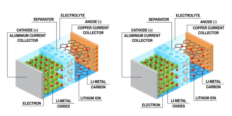
The cell is the basic electrochemical unit of a battery pack. Cells are connected in series to increase voltage and in parallel to increase capacity and current capability.
Cell selection usually starts with five questions:
- What nominal voltage and energy does the equipment require?
- What are the continuous and peak discharge currents?
- How much space and weight are available?
- What temperatures will the battery experience?
- What cycle life, safety, and certification requirements apply?
Cell Formats
Lithium-ion cells are commonly available in cylindrical, prismatic, and pouch formats. Each format trades off differently on sourcing, packaging density, and mechanical support:
| Format | Energy Density | Sourcing | Best Suited For |
|---|---|---|---|
| Cylindrical | Moderate | Standardized sizes, easy to source | Power tools, e-mobility, applications needing replaceable cells |
| Prismatic | High (volumetric) | Fewer standard sizes, longer lead times | Energy storage systems, industrial packs |
| Pouch | Highest (by weight) | Custom sizes common, needs compression support | Space-constrained or weight-sensitive designs |
- Cylindrical cells (e.g. 18650, 21700, 4680): Use a metal can and are available in standardized sizes. They can simplify sourcing and replacement, but a pack may require more interconnects and mechanical cell holders.
- Prismatic cells: Use a rigid rectangular housing and can make efficient use of enclosure space. They are often used in larger energy-storage and industrial packs.
- Pouch cells: Use a flexible laminated enclosure and can provide good packaging flexibility. They require careful compression, mechanical support, and protection from moisture and impact.
Battery Management System (BMS)
The battery management system is the control and protection layer of a lithium-ion battery pack. It monitors cell and pack conditions, makes protection decisions, and communicates battery status to the equipment or charger.
Depending on the pack, a BMS may provide:
- Cell voltage monitoring
- Pack current measurement
- Cell and pack temperature monitoring
- Overcharge and over-discharge protection
- Overcurrent and short-circuit protection
- Passive or active cell balancing
- State of charge and state of health estimation
- Charge and discharge control
- CAN, RS485, UART, or other communication interfaces
- Fault logging and service diagnostics
The BMS must match the cell chemistry, cell count, charge voltage, current limits, temperature range, charger, and communication protocol. A BMS designed for one chemistry or voltage configuration should not be reused in another pack without engineering review.
What Actually Separates a Good BMS from a Weak One
Most BMS datasheets list the same feature set, so the feature list alone does not tell you much about quality. The differences that matter usually show up at the component and test level rather than in the spec sheet headline numbers:
- Component selection: The MOSFET brand (for example, established suppliers like AOS or Infineon versus unspecified generic parts) and the sense resistor tolerance affect long-term protection accuracy and thermal reliability under repeated cycling.
- Verified testing: Documented short-circuit interruption test reports and high-temperature cycle-life validation indicate the protection thresholds have actually been confirmed under fault conditions, not just specified on paper.
- Protection architecture: The presence of a secondary, independent protection path in addition to the primary BMS, and whether balancing is active or passive, affects how the pack behaves if the primary controller fails or lags.
When evaluating a manufacturer’s BMS, ask for the bill of materials for key protection components and any available test reports, rather than relying on the feature list alone.
For more detail, see our guide to battery management systems.
Busbars, Interconnects, and Passive Components
Interconnects carry current between cells and the external terminals. They must be sized for the expected current, temperature rise, mechanical stress, and manufacturing method.
Busbars
Busbars are usually made from copper, aluminum, or plated metal. Their cross-section, length, connection method, and insulation affect resistance, heat generation, voltage drop, and electromagnetic behavior.
Cell Interconnects
Cylindrical cells may use nickel strips, copper components, or welded busbars. Prismatic and pouch cells may use bolted, welded, or laminated interconnects. Resistance welding, laser welding, and ultrasonic welding are selected according to the cell terminals, current, production volume, and quality requirements.
Fuses, Contactors, and Pre-Charge Circuits
Fuses provide protection against excessive current. Contactors allow the pack to disconnect the load or charger under defined conditions. A pre-charge circuit can limit inrush current when the battery is connected to equipment with large input capacitors.
These parts should be selected as part of the electrical architecture, not added after the cell layout is complete.
Battery Pack Enclosure and Mechanical Design
The enclosure protects the cells and electronics from impact, vibration, dust, moisture, and accidental contact. It also provides the mounting interface between the battery and the customer’s equipment.
A pack enclosure may need to provide:
- Structural support for cells and internal components
- Electrical insulation around terminals and busbars
- Mounting points and service access
- Protection against dust and water ingress
- Resistance to vibration, shock, and impact
- Space for connectors, sensors, fuses, and the BMS
- A defined thermal path from the cells to the cooling structure
Aluminum can provide good thermal conductivity and structural strength. Engineered plastics can reduce weight and support complex shapes. The best material depends on the required strength, heat dissipation, corrosion resistance, IP rating, cost, and production process.
Thermal Management Components
Cell temperature affects power output, charging behavior, efficiency, aging, and safety. Thermal management is therefore part of the battery architecture rather than a cosmetic enclosure feature.
Depending on the heat load and operating environment, a pack may use:
- Natural convection and conductive heat spreading
- Forced-air cooling with fans and ducts
- Thermal pads or gap fillers
- Liquid cooling plates or channels
- Resistive heating for cold-weather charging
- Temperature sensors connected to the BMS
The design should consider the worst-case discharge current, charging current, ambient temperature, installation airflow, and allowable cell temperature range. A BMS can detect temperature conditions, but it cannot compensate for an enclosure that cannot remove or add enough heat.
Wiring, Connectors, and Communication Interfaces
Wiring and connectors determine how the battery connects to the charger, inverter, motor controller, or host equipment. They also affect assembly time, serviceability, water resistance, and electrical safety.
When specifying these components, define:
- Continuous and peak current
- Voltage rating and insulation requirements
- Connector type and mating cycle requirement
- Cable length, gauge, bend radius, and routing
- Ingress protection and environmental sealing
- Communication protocol, baud rate, message format, and termination
CAN and RS485 are common choices for industrial and vehicle-related battery systems. The communication interface should be defined together with the equipment protocol, not selected only because it is common in the industry.
Testing and Quality-Control Components
Testing is part of the battery pack design. A reliable manufacturer should define how cells, subassemblies, and finished packs will be inspected and tested.
Typical checks may include:
- Incoming cell capacity, voltage, and internal-resistance checks
- Cell matching and consistency checks
- Weld strength and electrical-resistance checks
- Insulation and high-voltage tests where applicable
- BMS protection and communication tests
- Charge and discharge performance tests
- Temperature-sensor and thermal-protection tests
- Vibration, drop, sealing, or environmental tests when required
Certification and transportation requirements depend on the application and destination market. Common references include UN 38.3 for transport and UL or IEC standards for product safety. They should be identified early because they can affect cell selection, enclosure design, labeling, documentation, and production testing.
How Do These Components Work Together?
The components are interdependent. For example, increasing the discharge current may require larger cells, thicker busbars, higher-rated connectors, a different fuse, more thermal management, and a BMS with a higher current rating.
Reducing the enclosure size may require a different cell format, tighter thermal design, custom connectors, and a revised assembly process. Adding CAN communication may affect the BMS, wiring harness, firmware, testing, and equipment integration.
This is why a custom battery pack should be engineered as a complete system rather than assembled from a list of unrelated parts.
Applications and Safety Considerations
The same core components appear across very different applications, from electric vehicles and e-mobility to consumer electronics, stationary energy storage, and medical devices, but the design priorities shift with each one. An EV pack is built around high current and long cycle life with liquid cooling, while a consumer-electronics pack is built around low cost and compact size with simpler air cooling.
Across all applications, the same fault modes need to be designed against: external and internal short circuits, thermal runaway, overcharge, and mechanical damage such as crush or impact. The BMS, fuses, contactors, and enclosure work together to reduce these risks, but they cannot fully substitute for correct cell selection and mechanical design at the outset. See our guide on thermal runaway for a closer look at this failure mode.
What Should OEM Buyers Provide to a Battery Manufacturer?
A manufacturer can recommend the right components more efficiently when the initial specification includes:
- Nominal voltage and voltage limits
- Required capacity or runtime
- Continuous and peak discharge current
- Charging voltage, current, and charger type
- Maximum dimensions and weight
- Connector, cable, and mounting requirements
- Operating, charging, and storage temperatures
- Communication protocol and data requirements
- Ingress protection, vibration, and environmental requirements
- Cycle-life, certification, prototype, MOQ, and production targets
For supplier evaluation, see our guide on how to choose the best lithium battery manufacturer.
Frequently Asked Questions
Should I select the cells or the BMS first?
Define the electrical requirements (voltage, capacity, current, and temperature range) first, then select the cell chemistry and format. The BMS is chosen or designed to match the cell configuration, not the other way around. Selecting a BMS before the cells are finalized often forces a redesign.
What is a typical MOQ for a custom lithium-ion battery pack?
MOQ depends on cell format, enclosure tooling, and BMS customization. Battery packs built from standard cells and a configurable BMS can sometimes start at low prototype quantities, while packs requiring custom tooling or a fully custom BMS usually need a higher production commitment. Share your target volume early so the manufacturer can recommend the right approach.
Can an existing BMS design be reused with a different cell chemistry or voltage?
Not without engineering review. A BMS is configured for a specific cell chemistry, cell count, voltage window, and current range. Reusing a BMS outside its designed parameters can cause inaccurate protection thresholds or unreliable balancing.
What certifications does a custom battery pack need?
Requirements depend on the application and destination market. Common references include UN 38.3 for transport and UL or IEC standards for product safety. Certification needs should be defined before finalizing cell selection and enclosure design, since both can affect test outcomes.
How long does it take to get a custom battery pack quote?
A manufacturer can usually provide an initial recommendation within 1 to 2 business days once the voltage, capacity, current, dimensions, operating environment, and production volume are provided.
Conclusion
Lithium-ion battery pack components work as one system. Cells provide the energy, the BMS controls and protects the pack, interconnects carry current, the enclosure provides mechanical protection, thermal components manage heat, and connectors and communication interfaces integrate the battery with the equipment.
The best component selection depends on the application rather than on one specification alone. A successful design balances voltage, capacity, current, size, safety, service life, manufacturability, certification, and total cost of ownership.
If you are developing a custom lithium-ion battery pack, share your electrical, mechanical, environmental, and production requirements. Our engineers can recommend a practical component architecture and provide an initial solution within 1-2 business days.