
Le flotte AGV spesso subiscono arresti durante il sollevamento dei pallet. Questi riavvii sprecano 60 secondi per evento. I team operativi spesso incolpano il software. La causa è solitamente l'elevata resistenza interna nelle interconnessioni della batteria.
High resistance drags bus voltage below controller thresholds. High-discharge battery design solves this systemic failure.
Risposta diretta
High-discharge battery design focuses on maintaining low Direct Current Resistance (DCR). Low DCR ensures voltage stability during peak loads. Mobile robots pull 5C to 20C bursts.
At these rates, energy-optimized cells generate excessive Joule heat (I2R). The resulting voltage sag triggers under-voltage lockout (UVLO) or thermal protection cutoffs.
Successful designs use high-power pouch cells with wide tabs, pure copper interconnects welded ultrasonically, and a BMS sampling at 1 kHz. Industrial lithium battery packs must pass safety abuse tests per IEC 62619 (2022). Battery packs built around these principles reach 2,000 cycles at 5C continuous before hitting 80 percent State of Health (SOH).
Standard energy cells serve AGVs running at 1C continuous with short 2C bursts. The decision depends on the actual duty cycle. High-power packs trade 20 percent densità di energia for lower DCR. Log the real current profile for one full shift before selecting cell chemistry.
Punti chiave
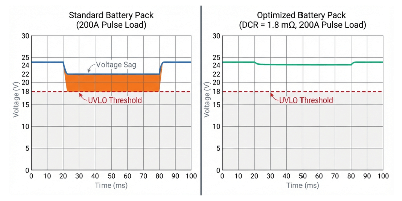
- Voltage sag from high DCR causes robot reboots. A 200A burst on a pack with 10 mΩ total loop resistance dumps 400W of heat internally. 24V logic rails drop below 18V within 3 seconds. Replacing nickel strip interconnects with oxygen-free copper busbars and ultrasonic welds reduces total pack DCR to 1.8 mΩ. Reboots stop.
- Standard BMS units sample too slowly for motor stall events. Off-the-shelf units sample at 10 Hz. Motor stall events occur within 50 milliseconds. A 1 kHz sampling BMS with CAN bus feedback to the motor controller throttles torque before cells reach 55 degrees Celsius. This prevents hard cutoffs and surprise shutdowns.
- High-power packs reduce total cost by 50 percent over 5 years. Standard energy cells degrade to 80 percent capacity in 500 cycles at 5C loads. High-power cells reach 2,000 cycles. The 35 percent higher upfront cost pays for itself within 14 months through reduced replacements and downtime.
Why High DCR Causes Robot Shutdowns
Internal resistance converts electrical energy into waste heat (P = I2R). Doubling the current quadruples the heat. In a robotic system pulling 200A peak, 10 mΩ of total loop resistance creates 400W of heat inside the battery pack enclosure.
Measurement Note: Data collected from 24V 100Ah NMC pouch pack at 25 degrees Celsius ambient. DCR measured via 10 ms pulse at 50 percent SOC per IEC 62620 method.
At 200A draw, a pack with 10 mΩ DCR drops 2V across the internal resistance. On a 24V nominal system, bus voltage sags to 22V under load. If the robot logic board has an 18V UVLO threshold, cold-start acceleration pushes the voltage past that limit. The controller resets. The robot stops.
Target total pack DCR below 2 mΩ for systems above 100A peak. DCR growth remains the primary aging mechanism in high-rate cycling. A cell starting at 0.8 mΩ drifts to 1.5 mΩ over 1,500 cycles at 5C. Designers must plan for end-of-life DCR. Cell DCR rises 30 percent at 0 degrees Celsius and 40 percent by end of life. Set beginning-of-life targets at 1.5 mΩ to maintain a safety margin.
Interconnect Engineering: Minimizing Loop Resistance
Interconnects contribute 30 to 50 percent of total DCR in many systems. Standard nickel strips and resistance spot welds create high-resistance bottlenecks.
Ultrasonic Metal Welding
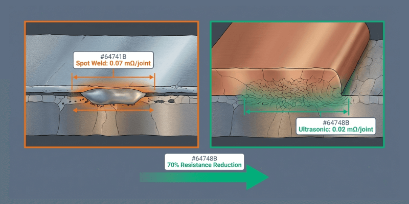
Ultrasonic welding creates a molecular bond between the cell tab and the busbar. Junction resistance for ultrasonic welds averages 0.02 mΩ per joint. Resistance spot welds average 0.07 mΩ. This represents a 70 percent reduction per connection point.
Copper Busbar Sizing
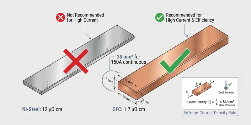
Standard nickel-plated steel has 7x higher resistivity than copper. High-discharge battery packs require oxygen-free copper (C11000). Use a cross-section rated for 5A per square millimeter or less for continuous load. A 150A continuous load requires 30 square millimeters of copper.
Redundant Parallel Paths
Parallel configurations lower per-string current and effective pack DCR. A 4P configuration at 200A total ensures each string handles 50A. This keeps cells on the stable portion of the polarization curve and reduces busbar heat. According to SAE J2464 (2021), engineers must verify interconnect integrity under both continuous and pulse loads.
BMS Architecture: 1 kHz Sampling and Feedback
Robot loads change faster than standard BMS hardware tracks. Real current waveforms have 200A spikes lasting 20 to 50 milliseconds during motor stalls or peak acceleration.
1 kHz Sampling Rate
The BMS must sample current every millisecond to catch motor stall events. Use dedicated current-sense amplifiers with 16-bit ADCs feeding the BMS microcontroller at 1 kHz. Slower sampling misses spikes. These spikes heat cells past safe limits.
Closed-loop CAN Bus Communication
The BMS must communicate with the motor controller. When cell temperatures reach 50 degrees Celsius, the BMS sends a CAN message requesting a torque limit reduction. At 55 degrees Celsius, the BMS commands a hard torque cap. This graduated response prevents shutdowns.
SOC Estimation Accuracy
Voltage-based State of Charge (SOC) estimation fails during high-discharge events. Voltage sags 2V under load and recovers over 30 seconds. Reading voltage during recovery leads to false SOC reporting. Use dedicated fuel gauge ICs with coulomb counting and drift compensation for 2 percent SOC accuracy.

Thermal Management for Sustained Operation
Warehouse robots run 16 to 20 hours daily. Heat from high-rate discharges accumulates in the pack core.
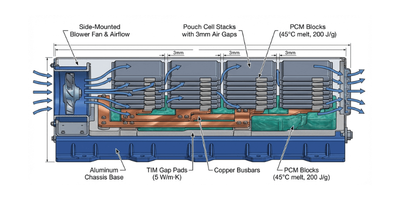
- Thermal Interface Materials (TIM). Use high-conductivity gap pads (5 W/mK) between busbars and the aluminum chassis. Without TIM, air gaps trap heat. Temperature differentials between busbars and the chassis reach 15 degrees Celsius.
- Phase Change Materials (PCM). PCM absorbs burst heat during 10C acceleration. Paraffin-based PCM with a 45 degree Celsius melt point absorbs 200 J/g during phase transition. PCM releases this heat slowly during return trips at 0.5C. Paraffin performance degrades over 2,000 cycles. Derate PCM capacity by 20 percent for long service life.
- Active Airflow Channels. Design internal pack spacing with 3 mm gaps between cell stacks. A blower fan controlled by the BMS forces air through these channels. This keeps peak cell temperatures below 50 degrees Celsius.
B2B Economic Impact: TCO Analysis
Selecting a low-power battery for a high-discharge robot increases Total Cost of Ownership (TCO).
| Cost Factor | Standard Energy Pack | High-Power Pack |
|---|---|---|
| Pack Unit Cost | 2,000 USD | 2,700 USD |
| Cycle Life at 5C | 500 Cycles | 2,000 Cycles |
| Replacements (5 Yr) | 4 Units | 1 Unit |
| Total Pack Cost | 8,000 USD | 2,700 USD |
| Reboot Downtime | 4,800 USD per year | 0 USD per year |
| 5-Year TCO per Robot | 32,000 USD | 14,700 USD |
High-power cells reduce the total cost of ownership by 54 percent. High-current heat accelerates SEI layer growth on the anode. Thicker SEI increases DCR. Standard energy packs reach 500 cycles to 80 percent SOH at 5C loads. High-power packs reach 2,000 cycles. Every voltage-sag reboot wastes 90 seconds.
A 20-robot fleet losing 200 picks monthly results in 10,000 dollars of efficiency loss. Selecting a partner with deep engineering capability in high-discharge systems (rather than simple assembly) is critical to realizing the TCO benefits mentioned above.

Troubleshooting Checklist
- Measure total pack DCR at terminals using a 10 ms pulse. If DCR exceeds 5 mΩ on a 24V system, interconnects are the bottleneck.
- Pull BMS logs for voltage dip events. Readings within 2V of the UVLO threshold indicate a future reboot.
- Inspect interconnects for heat damage. Discoloration on nickel strips indicates high resistance.
- Check temperature spread. Gradients above 5 degrees Celsius point to wiring imbalance.
- Log the shift current profile. If peak current exceeds 80 percent of the rated burst, cells are overloaded.

Optimize Your Robotics Power Platform
This article outlines design principles and business value for high-discharge battery systems.
Every robotic platform is unique. The optimal power solution requires customization. Holo Battery provides comprehensive battery solutions for leading mobile robot manufacturers from conceptual design and prototype testing to mass production. Our engineering team offers free TCO analysis and preliminary design proposals based on your specific load profile and spatial constraints.
Next Step: Send your robot current curve data and spatial dimension requirements to sales@holobattery.com. Our engineers will respond within 24 hours.
FAQ
Why does the robot logic board reset during lifting?
Battery voltage sags below the UVLO threshold. This occurs when total battery pack DCR is too high for the peak current. Inspect all interconnects for high-resistance joints. Measure total loop resistance at the terminals under a 10 ms pulse load.
Is LFP a good fit for high-power robots?
High-power LFP variants serve robotics well if the system allows extra weight. LFP voltage stability helps maintain UVLO margin. The trade-off is 20 percent lower energy density by weight compared to NMC.
Should you use supercapacitors for peak loads?
Supercapacitors handle 1 to 5 ms spikes like motor startup inrush. They fail to support sustained lift operations lasting 2 to 10 seconds. Focus on lowering battery DCR through better cells and interconnects first.