


Ingenieure können unsichtbare Probleme nicht beheben. Verbesserung Schiffsbatterie Zuverlässigkeit erfordert die methodische Zerstörung ausgefallener Einheiten.
Zwischen 2024 und 2025 führte das forensische Team von Holo Battery systematische Teardowns an 300 ausgefallenen IP68-Schiffsbatteriesätzen globaler Lieferanten durch. Bei unseren Abrissbeobachtungen zeigten alle von uns erhaltenen Rucksäcke ein Ausfallverhalten im Feld, das mit dem Einsatz auf See vereinbar ist.
Hinweise zu Datensätzen und Messungen: Die in diesem Artikel besprochenen Häufigkeiten und Zeitfenster basieren auf beobachteten Mustern aus dem Teardown-Datensatz und sollten als Richtwerte betrachtet werden. Alle mikroskopischen Dimensionsangaben werden als Größenordnungsbeobachtungen aus der visuellen Überprüfung und nicht als Präzisionsmessungen dargestellt. Diese genauen Beobachtungen bilden die empirische Grundlage für unsere Master-Leitfaden für fortgeschrittene Vergusstechnik.
Anstatt sich auf theoretische Fehlermodelle zu verlassen, hat unser Team physikalische Beweise mithilfe von Mikroskopie und Elektronenbildgebung kartiert. Dieses Dokument stellt Hardwarearchitekten direkte forensische Daten zu kapselungsbedingten Fehlern, Salzwassereintrittspfaden und den typischen Lebensdauersignalen bereit, die in Standard-Schiffsstromversorgungssystemen auftreten.
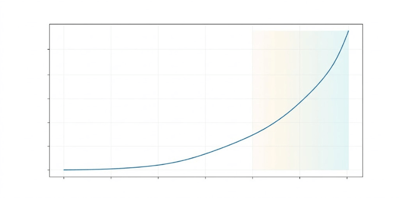
Die 18-monatige Todeskurve
Die Analyse des Teardown-Datensatzes ergab ein deutliches chronologisches Muster. Die meisten eFoil- und ROV-Akkus überstehen das erste Betriebsjahr. In den ersten 12 Monaten sind die Gewährleistungsansprüche häufig geringer. In den von uns untersuchten Fällen konzentriert sich die Fehleraktivität typischerweise auf ein Zeitfenster von 14 bis 18 Monaten.
Beim Standard-IP68-Test werden definierte Tiefen- und Zeitbedingungen verwendet. Statische Labortests reproduzieren die im Feld beobachteten dynamischen Druckwechsel, extremen Temperaturschocks und den kontinuierlichen Salzkristallabrieb nicht vollständig. Im Laufe der Zeit werden Standard-Vergusssysteme durch dynamische Zyklen beeinträchtigt. Sobald sich in der Harzmatrix interne Rissbildungspfade bilden, werden in diesem Probensatz häufig das Eindringen von Salzwasser und das Verhalten am Ende der Lebensdauer in Verbindung gebracht.
Minimal störende Beweisextraktion
Das Abreißen eines festen Blocks aus ausgehärtetem Polyurethan oder Epoxidharz erfordert spezielle Techniken. Durch herkömmliches mechanisches Schneiden mit Sägen oder Schleifmaschinen werden genau die Mikrorisse und Schnittstellennachweise zerstört, die wir dokumentieren möchten.
Fluoreszierende Farbeindringprüfung
Vor dem Öffnen des Gehäuses setzen Techniker die Packung mit einem niedrigviskosen Fluoreszenzfarbstoff unter Druck. Der Farbstoff bleibt über längere Zeiträume unter Druck.
Chemische Harzauflösung
Das Team verwendet kontrollierte Lösungsmittelbäder, die speziell auf die Vergusschemie abgestimmt sind. Diese Lösungsmittel lösen die Harzmatrix mit kontrollierten, langsamen Auflösungsgeschwindigkeiten auf.
UV-Mikroinspektion
Sobald das BMS und die Zellanordnungen aus dem Lösungsmittel herauskommen, prüfen Ingenieure die Baugruppe unter ultraviolettem Licht. Der fluoreszierende Farbstoff hilft, mögliche Eintrittswege zu empfindlicher Elektronik hervorzuheben.
Mikroskopischer Beweis 1: Hohlraumbedingte Frakturen
Unser forensisches Team beobachtete die Ausbreitung von Hohlräumen in einer großen Teilmenge der fehlerhaften Proben.
Physische Signatur
Unter dem optischen Mikroskop wurden Hohlraumansammlungen als kugelförmige Strukturen beobachtet, die im ausgehärteten Harz eingeschlossen waren. Diese Hohlräume waren häufig in der Nähe starrer Strukturen wie Stromanschlusspfosten und Hauptkabelbaumübergängen konzentriert. Unter UV-Licht zeigte Farbeindringmittel Rissnetzwerke, die die Hohlraumbereiche verbinden.
Beweiszeiger
Die Bruchmorphologie stimmt mit eingeschlossenen Gastaschen überein, die während thermischer Abfälle örtlicher Scherspannung ausgesetzt sind.
Implication for validation: Procurement teams should demand customer-readable whole-pack airtightness or leak verification reports, alongside encapsulation process traceability that demonstrates controlled vacuum/degassing practices designed to minimize void risk. Also request end-of-line integrity verification after the full build process (not only early-stage checks).

Microscopic Evidence 2: Capillary Delamination
We traced primary water ingress to boundary delamination across multiple samples.
Physische Signatur
Ingenieure untersuchten die Schnittstelle zwischen dem Aluminium-Außengehäuse und dem inneren Vergussharz. Auf glatten Aluminiumoberflächen wurde in den untersuchten Regionen eine minimale chemische Bindung beobachtet. Entlang Abschnitten der Gehäusewand wurde ein im mikroskopischen Maßstab (in der Größenordnung von mehreren zehn Mikrometern) sichtbarer Grenzflächenspalt beobachtet. UV-Farbstoff zeigte Salzwasser, das sich entlang dieses Grenzkanals bewegte.
Beweiszeiger
Glatte Grenzkanäle deuten auf eine unzureichende Schnittstellenbereitschaft vor dem Auftragen und Aushärten des Harzes hin.
Implication for validation: Procurement teams should request interface integrity evidence (e.g., adhesion performance where applicable), together with customer-readable whole-pack airtightness or leak verification reports and post-encapsulation integrity verification after final assembly. The goal is to confirm the delivered boundary remains sealed throughout the complete manufacturing workflow.
Microscopic Evidence 3: Dendritic Copper Growth
Corrosion degraded the Battery Management System in a notable fraction of the teardowns.
Physische Signatur
Technicians used scanning electron microscopy to examine the BMS PCBs. Widespread copper oxidation was observed. More critically, conductive copper dendrites were seen bridging small gaps between surface mount components. In some cases, the potting compound covering the boards was observed to be softer than surrounding rigid regions.
Beweiszeiger
Widespread dendritic growth under visually intact encapsulation indicates long-term moisture vapor permeation and transport to sensitive conductor networks.
Implication for validation: Procurement teams should request traceability evidence for dedicated moisture-protection steps used by the supplier (e.g., conformal coating execution where applicable) and verify that program-aligned post-encapsulation electrical/functional verification is performed after the fully sealed assembly, alongside customer-readable whole-pack leak verification.
Beweise für die Säulenkartierung
Diese forensischen Beobachtungen lassen sich direkt auf die grundlegenden technischen Fehlermodi zurückführen, die im Advanced Potting Engineering-Framework beschrieben sind.
- Durch Hohlräume verursachte Brüche sind auf Hohlräume im Modus 2 und Nichtübereinstimmung des WAK im Modus 3 zurückzuführen, die zur Belastung beitragen.
- Kapillare Delaminierung in Kombination mit Salzspuren entspricht Mode 6 Delaminierung und Kapillareintritt.
- Kupferdendriten aus Feuchtigkeitspfaden werden der Feuchtigkeitspermeation im Modus 6 zugeordnet.
- Je nach Material und Betriebsprofil können weichere örtliche Harzbereiche mit den thermischen Einschlusseffekten von Modus 1 oder einer durch exotherme Aushärtung verursachten Verschlechterung im Modus 4 korrelieren.
Die finanzielle Realität von Feldausfällen
Die Daten haben praktische finanzielle Auswirkungen für Beschaffungsteams.
| Forensische Kategorie | Beobachtungshäufigkeit | Typische Zeit bis zum Ausfall (beobachteter Cluster) | Forensischer Marker |
|---|---|---|---|
| Leere Brüche | 45 Prozent | 12–16 Monate | Interne Mikrorisse |
| Delaminierung | 25 Prozent | 14–18 Monate | Grenzwasserwege |
| Dampfpermeation | 20 Prozent | 18–24 Monate | Kupfer-SMT-Dendriten |
| Thermischer Schaden | 10 Prozent | 6–12 Monate | Sprödes/verbranntes Harz |
Der Kauf kostengünstiger Schiffsbatterien führt oft zu teuren Garantie-Austausch- und Sicherheitsaufwendungen. Ein einzelner fehlgeschlagener Austausch einer eFoil-Batterie kostet in der Regel mehr als 2.000 USD, wenn die Ersatzlogistik und die Handhabung gefährlicher Transporte berücksichtigt werden. Darüber hinaus erfordert der Versand beschädigter Lithiumbatterien spezielle und oft kostspielige Frachtprotokolle.
Abschluss
IP68 dient als Basisanspruch, aber die tatsächliche Zuverlässigkeit im Seeverkehr hängt davon ab, ob die gelieferten Verguss- und Grenzschnittstellen die spezifischen Fehlerpfade kontrollieren, die durch Teardown-Beweise aufgedeckt werden.