


Les équipements marins à haut débit doivent fournir une puissance élevée pendant de longues périodes. Les systèmes tels que l’eFoil et la robotique sous-marine consomment des courants continus élevés à l’intérieur d’enceintes scellées. Quand le enceinte est scellé et que le matériau d'enrobage n'est pas conçu pour le flux de chaleur, la chaleur générée à l'intérieur de la batterie peut être piégée. Cela augmente l'usure et peut accélérer la défaillance, en particulier dans les zones les plus chaudes du système. paquet de batterie.
De nombreux fournisseurs donnent la priorité à la prévention des infiltrations d’eau. Pour des charges de décharge élevées, le système d'enrobage peut involontairement réduire le transport de chaleur. Ce problème de fiabilité est connu sous le nom de piégeage thermique. Ce guide de cluster se concentre sur la façon de concevoir l'empotage afin qu'il prenne en charge le flux de chaleur et sur la manière de le valider avec l'acquisition de preuves que les équipes CTO peuvent demander. L'article est une extension directe de notre guide des piliers Fiabilité des batteries marines IP68 : ingénierie d'empotage.
Le principal risque : le flux de chaleur peut devenir déséquilibré
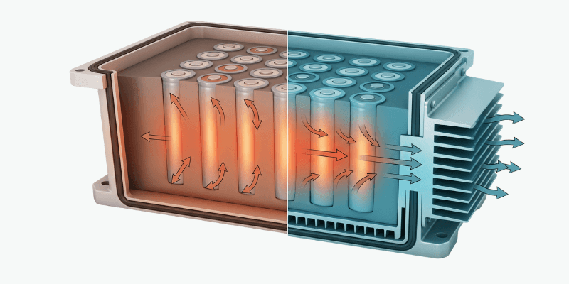
Pendant la décharge, la batterie génère de la chaleur dans la pile de cellules et dans les chemins de courant électrique. La batterie doit évacuer cette chaleur à travers le chemin thermique créé par le système d’enrobage et le boîtier.
La fiabilité dépend de deux questions :
1) Quelle quantité de chaleur la batterie génère sous le profil de service
2) Avec quelle efficacité la chaleur est-elle évacuée à travers le conception de la batterie
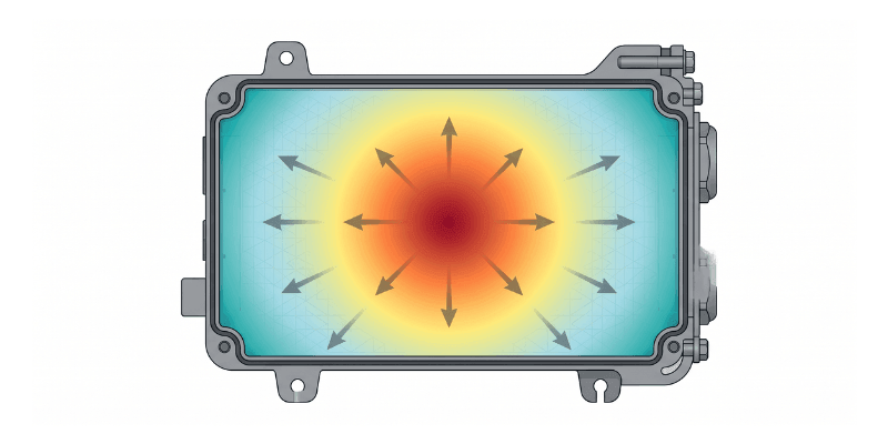
La conception de l’empotage a un impact sur la deuxième question. Si l'empotage ne permet pas un contact thermique et un transport de chaleur constants, les régions centrales ou les points chauds peuvent devenir plus chauds que prévu. Des températures plus élevées accélèrent le vieillissement et augmentent la résistance interne au fil du temps. Cela peut entraîner une accumulation supplémentaire de chaleur au cours des cycles ultérieurs, créant ainsi une boucle de rétroaction.
Dans les missions de démontage, nous constatons souvent des schémas de vieillissement non uniformes cohérents avec un piégeage thermique. Dans le pire des cas, la température peut dépasser les limites définies par la fiche technique de la cellule et la stratégie de protection. Cela augmente la probabilité d’une fin de vie précoce ou d’événements de protection.
Comment penser à l'empotage pour les droits à taux élevé
Pour la prise de décision en matière de CTO et d’approvisionnement, l’objectif est simple. Le système d’empotage doit se comporter comme une voie thermique active, et non comme un simple joint.
Une conception fiable à haut débit nécessite généralement quatre leviers alignés.
1) Sélection des matériaux : conductivité thermique et stabilité
Ne présumez pas que « toute résine imperméable fonctionne ». Les architectures à haut débit nécessitent souvent des systèmes thermoconducteurs en polyuréthane ou en silicone conçus pour le transport de chaleur.
Détails de l'approvisionnement : les fournisseurs doivent fournir des preuves de performances thermiques, et pas seulement des déclarations marketing.
2) Contact thermique : évitez les vides et le mauvais mouillage
Même un matériau d'enrobage thermiquement conducteur peut échouer en tant que voie thermique s'il laisse des vides ou n'établit pas de contact fiable autour des sources de chaleur critiques.
Les objectifs de conception incluent :
- bon mouillage aux interfaces critiques
- risque de vide minimisé pendant le mélange et la distribution
- géométrie d'enrobage qui prend en charge un flux de résine constant autour de la pile de cellules et des structures rigides
3) Architecture : réduire les goulots d'étranglement thermiques
L’épaisseur et la géométrie de l’empotage affectent la résistance thermique. Les conceptions à usage intensif évitent généralement les volumes d’enrobage isolants épais autour des régions les plus chaudes.
La limite d’empotage doit créer un couplage thermique cohérent entre :
- régions productrices de chaleur, telles que la pile de cellules et les chemins de courant
- les surfaces du boîtier qui font office de dissipateur thermique
Certaines conceptions incluent également des caractéristiques structurelles internes qui améliorent le transfert de chaleur tout en conservant la fiabilité de l'étanchéité.
4) Gestion de la cure exothermique : protéger les cellules pendant la fabrication
Thermally conductive resins can generate additional heat during curing. Thick pours increase the risk of exotherm and early temperature stress.
Cure risk controls should include:
- temperature-aware manufacturing discipline
- temperature monitoring where appropriate
- cure profile traceability tied to program acceptance
Acceptance should be defined against the cell temperature limits and the program’s reliability targets.
Procurement Validation Metrics: Evidence You Can Request
Thermal claims must be validated with data that matches marine duty conditions. “CAD simulation” is not enough for thermal trapping risk.
During supplier evaluation, request evidence in four categories:
| Evidence Category | What to Request | How It Is Validated | Pass Criteria (Program-defined) |
| Resin heat transport | Preuve d'essai de conductivité thermique ou dossier d'essai de matériau équivalent | Testé sur des échantillons durcis représentatifs en utilisant l'épaisseur divulguée | Répond aux objectifs du programme pour le transport de chaleur dérivé de la conception de service |
| Température maximale du point chaud | Enregistrement thermique au niveau de l'unité | Décharge continue à pleine charge représentative du service | Reste dans les limites de température des cellules avec une marge basée sur la tolérance au risque de votre programme |
| Uniformité de la température | Cartographie de température multipoint | Thermocouples ou capteurs équivalents dans des régions chaudes représentatives | Le delta des points chauds reste dans les limites définies par le programme |
| Guérir de la sécurité exothermique | Guérir l’enregistrement thermique et la traçabilité des lots | Enregistré pendant la phase de durcissement dans des conditions de processus définies | Ne dépasse pas les limites de température des cellules et de l'assemblage pour la masse de polymérisation et la géométrie définies |
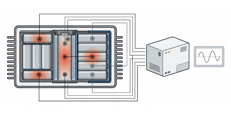
Implication pour la validation : les fournisseurs doivent fournir des données d'enregistrement thermique au niveau de l'unité, y compris le placement des capteurs et le temps de stabilisation, à partir de tests de prototypes représentatifs. Ils doivent également fournir une traçabilité du processus d'encapsulation montrant un dégazage et un mélange contrôlés, ainsi qu'un comportement de durcissement contrôlé. La vérification de l’intégrité en fin de chaîne doit faire partie de l’ensemble des preuves fournies.
Conclusion
Pour les applications marines à haut débit, la conception de l'enrobage doit prendre en charge le flux de chaleur dans le cadre du profil de fonctionnement réel. Le risque de piégeage thermique peut être réduit lorsque la formulation d'enrobage, la géométrie, la répétabilité du durcissement et du processus sont validées avec des preuves que les équipes CTO et achats peuvent examiner.