

If you specify or source lithium-ion batteries, understanding the fundamentals is not optional. Cell selection, pack design, and battery management decisions affect product safety, warranty costs, and operational lifespan, directly and for years after the purchase order is signed.
This guide covers how lithium-ion batteries work, what causes them to fail, and what it takes to prevent failure in commercial and industrial applications. We write it from the manufacturing side: what we check during cell qualification and production inspection, and what we ask customers to have ready before we start engineering a pack.
In short: a lithium-ion cell stores energy by moving lithium ions between a graphite anode and a metal oxide or phosphate cathode through a liquid electrolyte. NMC gives the highest energy density. LFP gives the best thermal stability and the longest cycle life. And nearly every failure mode covered below is preventable, through cell sourcing, pack design, and BMS protection settings, rather than bad luck.
Why Lithium-Ion Batteries Are the Dominant Choice
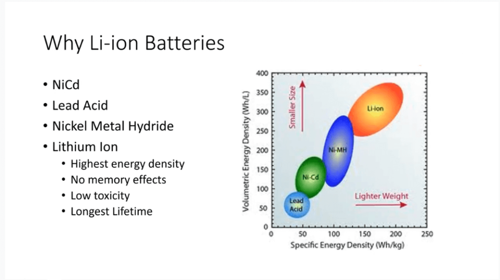
Lithium-ion batteries have displaced lead acid, nickel cadmium, and nickel metal hydride chemistries across most applications, and it did not happen by accident. The reasons come down to energy density, cycle life, and running cost.
Energy density
| Chemistry | Gravimetric Energy Density |
| Lead acid | 30 to 50 Wh/kg |
| Nickel cadmium | 40 to 60 Wh/kg |
| Nickel metal hydride | 60 to 120 Wh/kg |
| Lithium-ion (NMC) | 150 to 220 Wh/kg |
| Lithium-ion (NCA) | 200 to 260 Wh/kg |
| Lithium iron phosphate (LFP) | 90 to 160 Wh/kg |
No Memory Effect
Unlike nickel-cadmium, lithium-ion cells suffer no “memory effect.” They can be charged or discharged at any state without long-term capacity loss, simplifying charge management in variable duty cycles.
Longer Cycle Life & Deeper Usable Capacity
Lithium-ion batteries outlast lead acid and nickel based chemistries in high cycle applications, sometimes by a wide margin.
LFP cells in particular can exceed 3,000 cycles at 80 percent depth of discharge, where a lead acid battery in the same duty cycle might reach a few hundred.
Why the gap is so large: lead acid typically needs to stay above roughly 50 percent state of charge to protect its cycle life, while lithium-ion can safely use 80 to 100 percent of its rated capacity. See what is battery cycle life for how depth of discharge and charge rate change that number in practice.
Lower Toxicity
LFP batteries contain no cobalt or heavy metals, so they’re lower toxicity than cobalt based lithium-ion chemistries.
Lower Self-Discharge
Lithium-ion cells self discharge at 1 to 3 percent per month. Nickel cadmium and nickel metal hydride cells lose 10 to 15 percent per month just sitting on a shelf. That difference matters for backup power and seasonal equipment.
Replacing a Lead Acid System?
Buyers moving off lead acid, in forklifts, backup power units, standby systems, and marine equipment, ask a more specific question than “which chemistry has higher energy density.”
Lead acid’s discharge voltage drops steadily across its discharge. A lithium-ion pack holds a flat voltage output until near full depletion, and needs no water top-off or equalisation charging.
Flat voltage, deeper usable capacity, no maintenance: that combination is why a lithium-ion pack rated at a given capacity delivers more usable energy, in a smaller and lighter enclosure, than a lead acid battery of the same rated capacity. For the full breakdown, including energy density, charging time, temperature performance, storage, and total cost, see lithium vs. lead acid: choosing the right battery.
How Lithium-ion Batteries Work
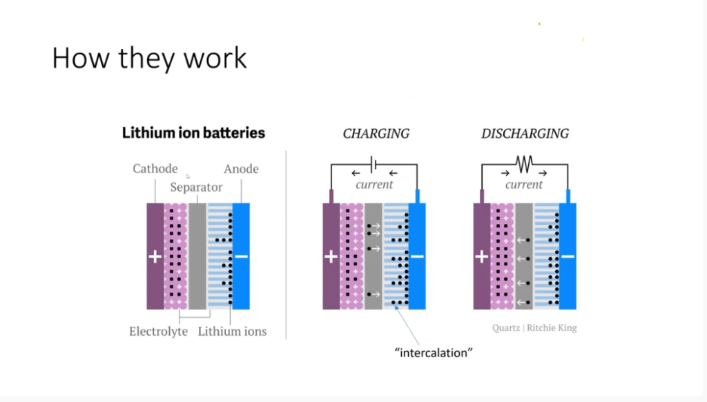
A lithium-ion cell has four core components. For how those components come together into a finished pack, including busbars, enclosures, and connectors, see the ultimate guide to lithium-ion battery pack components.
| Component | Material | Function |
| Cathode | Lithium metal oxide (LCO, NMC, NCA, LFP) | Stores and releases lithium ions |
| Anode | Graphite | Receives and releases lithium ions |
| Electrolyte | Lithium salt (typically LiPF6) dissolved in an organic carbonate solvent | Conducts lithium ions between electrodes |
| Separator | Polyethylene or polypropylene | Keeps the cathode and anode from touching |
Charging drives an external power source to push lithium ions out of the cathode material. The ions travel through the electrolyte and insert into the graphite anode, while electrons flow through the external circuit from cathode to anode at the same time.
Discharge just reverses it. Lithium ions leave the graphite anode and travel back through the electrolyte to the cathode, electrons flow through the external circuit the other way, and that electron flow is what powers the load.
This reversible movement of ions between electrodes is what makes lithium-ion batteries rechargeable. It’s also the chemistry that earned John Goodenough, M. Stanley Whittingham, and Akira Yoshino the 2019 Nobel Prize in Chemistry.
Common Cathode Chemistries
The cathode material has the biggest influence on a cell’s performance, safety, and cost.
Lithium Cobalt Oxide (LCO)
High energy density, relatively low thermal stability. Used mainly in consumer electronics such as smartphones and laptops, where energy density is the priority and battery size is constrained. Less common in industrial or high cycle applications, because of shorter cycle life and higher sensitivity to heat.
Lithium Manganese Oxide (LMO)
Better thermal stability than LCO. Used in some EV applications and power tools, though it has lower energy density than NMC or NCA.
Lithium Nickel Cobalt Aluminum Oxide (NCA)
Very high energy density, used in high performance EV applications. Needs strong thermal management, because of higher sensitivity to heat.
Lithium Nickel Manganese Cobalt Oxide (NMC)
The most widely used chemistry in industrial and commercial EV applications. It balances energy density, cycle life, and thermal stability well, and comes in several ratio variants (NMC 111, NMC 532, NMC 622, NMC 811), each trading off energy density against thermal stability and cost.
Lithium Iron Phosphate (LFP)
Lower energy density than NMC or NCA, but noticeably better thermal stability and cycle life. No cobalt content, which reduces raw material cost and supply chain risk. This is the preferred choice for stationary storage, commercial EVs, marine equipment, and industrial applications, anywhere safety margin and cycle life matter more than compact size. For a full side by side breakdown, see LFP vs NMC: engineering comparison guide.
| Chemistry | Energy Density | Cycle Life | Thermal Stability | Cobalt Content |
| LCO | High | Moderate | Lower | Yes |
| LMO | Moderate | Moderate | Good | No |
| NCA | Very high | High | Moderate | Yes |
| NMC | High | High | Good | Yes |
| LFP | Moderate | Very high | Excellent | No |
What Causes Lithium-Ion Battery Failure
Anyone specifying, designing, or operating lithium-ion battery systems needs to understand these seven failure mechanisms. For a closer look at how these show up as field returns and warranty claims, see causes of lithium battery pack failure and understanding li-ion battery safety.
1. Electrolyte Evaporation and Pressure Buildup
The organic electrolyte in a lithium-ion cell has a relatively low boiling point. If the cell reaches excessive temperatures, typically above 60°C sustained, the electrolyte starts to evaporate and generate gas, which raises internal pressure and causes the cell to swell or bulge.
A swollen cell is a warning sign of dangerous conditions and must be taken out of service immediately.
2. Separator Melting
The separator between cathode and anode is usually polyethylene, polypropylene, or a layered combination of both. Polyethylene starts to soften and shut down around 130 to 135°C, closing its pores to stop ion flow before things get worse. Polypropylene holds its structure to a higher temperature, around 165°C. That’s why many commercial separators sandwich a polyethylene layer between polypropylene layers: the polyethylene shuts down early while the polypropylene keeps the physical barrier intact a bit longer.
When the separator melts through, or is breached by another failure mode, the cathode and anode make direct contact and create an internal short circuit. That generates heat rapidly and can trigger thermal runaway.
3. Oxygen Release and Thermal Runaway
At high temperatures, oxide based cathode materials, including LCO, LMO, NMC, and NCA, release oxygen. That oxygen reacts with the evaporated electrolyte and triggers an uncontrolled exothermic reaction. The heat from that reaction accelerates further oxygen release and electrolyte breakdown, and the cycle feeds itself: that’s thermal runaway. Once it starts, it’s extremely difficult to stop without outside intervention.
LFP cells resist thermal runaway far better than the alternatives, because the iron phosphate structure doesn’t release oxygen under thermal stress.
4. Overcharging and Dendrite Formation
Charging a cell past its maximum voltage forces excess electrons to combine with lithium ions at the anode surface, instead of letting those ions insert properly into the graphite structure. This forms lithium metal deposits called dendrites, which grow through the electrolyte over time and can pierce the separator, creating an internal short circuit.
Accurate voltage monitoring and overcharge protection in the battery management system is the primary defence against this failure mode.
5. Lithium Plating From Charging in Cold Temperatures
At low temperatures, lithium ions move more slowly through the electrolyte. Charging at high current in cold conditions asks ions to insert into the graphite anode faster than they physically can, so the excess lithium deposits on the anode surface as metallic lithium instead of being absorbed into the graphite.
This plating reduces capacity permanently, and it can also create a short circuit risk if the deposits grow through the separator.
Any application operating in cold environments needs charge protection tied to temperature. The general rule: cut charge current well below 0°C, and avoid charging altogether below -20°C for most lithium-ion chemistries.
6. Discharging Below the Minimum Voltage
Pulling a lithium-ion cell below its minimum voltage causes the copper current collector on the anode to start dissolving into the electrolyte. When the cell is recharged afterward, that dissolved copper can redeposit, but not as the original uniform foil. Irregular copper deposits create internal short circuits.
The battery management system has to enforce a minimum cell voltage cutoff to prevent this. For most lithium-ion chemistries that floor sits at 2.5 to 2.8V. For LFP, the typical floor is 2.5V.
7. Manufacturing Defects and Contamination
Particulate contamination introduced during cell manufacturing is one of the most common causes of early life cell failure. Metal particles or other contaminants inside a cell create localised internal short circuits that show up as capacity loss, unusual self discharge, or, in severe cases, a thermal event.
Sourcing cells from manufacturers with documented, verifiable quality control is a procurement decision that affects safety, not just a line item on cost.
Preventing Battery Failure: Three Lines of Defence
Line 1: Cell Quality
Cell quality is the foundation everything else sits on. Not all cells built to the same specification perform the same way; differences in process control, raw material purity, and inspection standards show up as real differences in field reliability.
When evaluating cell suppliers:
- Request and verify UN 38.3 transport test reports.
- Confirm cell level certifications such as UL 1642 or IEC 62133.
- Assess the manufacturer’s quality management system at the facility level.
- Request capacity and internal resistance data across a full production batch, not just a handful of samples.
- Understand how the supplier inspects incoming raw materials.
Line 2: Battery Pack Design
A well designed pack manages heat, spreads current evenly, and contains the consequences of a single cell failure.
Thermal management. Cells generate heat during charge and discharge, and without a way to remove that heat, it builds up between cells and accelerates degradation. High power applications typically need active cooling, either liquid or forced air.
Current distribution. In parallel cell configurations, uneven cable routing and contact resistance cause some cells to carry more current than others, which leads to uneven aging across the pack. Busbar design and cable routing should be engineered specifically to minimise that imbalance.
Fault containment. Pack design should limit how far a single cell thermal event can spread to neighbouring cells. Cell spacing, thermal barriers, and venting paths are the standard tools here.
Cell matching. Cells within a pack should be matched for capacity and internal resistance, because mismatched cells wired in series create imbalance and wear out the weaker cells faster.
Line 3: Battery Management System
The battery management system is the primary active protection layer. A properly specified BMS monitors cell level parameters in real time and steps in before conditions turn into failure.
Voltage Protection
Overvoltage protection disconnects the charge circuit when any cell hits its maximum voltage, typically 4.20V per cell for NMC and 3.65V per cell for LFP.
Undervoltage protection disconnects the load when any cell drops below its minimum voltage, typically 2.5 to 2.8V for most lithium-ion chemistries and 2.5V for LFP.
Current protection at the pack level matters too, not just at the individual cell level: sustained overcurrent generates heat in cables and contacts regardless of what any single cell’s voltage reads.
Temperature Protection
High temperature cutoff disconnects charge and discharge when cell temperature exceeds safe limits, typically 45 to 50°C for charging and 60 to 70°C for discharging, depending on chemistry.
Low temperature charge protection stops charging below the minimum safe temperature for the chemistry in use. Most lithium-ion cells should not charge below 0°C at standard rates, though some cells with specific electrolyte formulations tolerate limited charging down to negative 20°C at reduced current. Confirm the actual minimum with the cell manufacturer and set the BMS accordingly, since this varies by product.
Cell Balancing
Cells wired in series drift apart in state of charge over time, because of small manufacturing differences in capacity and self discharge rate. Without balancing, that drift accumulates until the weakest cell caps the performance of the entire pack.
Passive balancing bleeds excess energy from the higher charged cells through resistors as heat. It’s simple and cheap, but wastes energy on large imbalances.
Active balancing moves energy from the higher charged cells to the lower charged ones. It costs more and adds complexity, but it’s the better choice for large series strings or applications where maximum cycle life matters.
Manufacturing Insights: What This Looks Like on the Production Floor
Understanding the failure modes above is one thing. Catching them across a production run of several thousand packs is another. Here’s what the three lines of defence look like in practice on our line.
Cell qualification happens before a single pack is built. Chemistry and format (cylindrical, pouch, or prismatic) get selected against the application’s power, cycle life, and thermal requirements first, not against whichever cell is cheapest that quarter. Candidate cells go through head-to-head benchmarking on energy density, specific power, cycle life, and safety before a supplier is finalised. For the full cell selection and qualification process, see custom lithium battery pack manufacturing: a technical end-to-end process guide.
Three inspection checkpoints, not one. Incoming Quality Control (IQC) checks cell capacity, voltage profile, and grading before any cell enters the line. In-Process Quality Control (IPQC) tracks statistical process control parameters and defect rates at each assembly step. Final Product Quality Control (FPQC) covers dimensional inspection, capacity and internal resistance testing, and inline X-ray inspection of internal weld and interconnect quality before a pack ships. Fail any of these three checkpoints, and the cell or pack doesn’t go out the door.
Cell grading documentation is worth requesting and verifying independently. Cells coming off a fabrication line get graded and binned by tested capacity, impedance, and voltage profile, and not every cell meets top-tier spec. Grade B cells sold as Grade A is a documented fraud pattern in the cell supply chain. See battery cell grading: how to spot Grade B fraud in your supply chain for how to catch it before it reaches your product.
Assembly tolerances compound across a pack. Bus bars get torqued to exact specifications and audited during the process. Thermal interface material placement, conformal coating, and potting are all done against defined acceptance criteria. Why so strict: a small variation per cell becomes a real reliability gap once it’s multiplied across a pack of a few hundred cells, let alone a production run of a few thousand packs.
Relevant Standards
Knowing which standards apply to a product matters for compliance and market access. For how UN 38.3, IEC 62133, and IEC 62619 differ and which one your product actually needs, see UN38.3 vs IEC 62133 vs IEC 62619: battery compliance guide for OEM buyers.
Cell Level
| Standard | Scope |
| UL 1642 | Safety standard for lithium batteries, widely required in North America |
| IEC 62133 | International standard for portable sealed secondary lithium cells and batteries |
Pack Level
| Standard | Scope |
| UL 2054 | Household and commercial batteries, requires UL 1642 compliance as a prerequisite |
| UL 1973 | Batteries for stationary and motive applications, requires UL 1642 as a prerequisite |
| IEC 62619 | Safety requirements for industrial and stationary lithium batteries, covering cell, module, pack, and system level |
| IEC 62133 | Covers cells and packs for portable applications |
BMS Hardware and Software
| Standard | Scope |
| UL 991 | Safety related controls for hardware |
| UL 1998 | Software in programmable components |
| IEC 60730-1 | Automatic electrical controls, applicable to BMS software |
Transport
| Standard | Scope |
| UN 38.3 | Transport testing required for shipping lithium batteries by air, sea, or road |
UL 991 and UL 1998 are not prerequisites for UL 2054 or UL 1973 pack listings. If a BMS is not separately listed to these standards, fault condition testing is required to show that BMS failures do not create dangerous conditions. That testing happens as part of the pack level certification process. Confirm the exact requirements with a certification body based on target markets and application.
Ready to Specify a Pack? What We Need From You, and What Happens Next
Information to have ready before you request a quote. The faster we can qualify cells and start engineering against real requirements, the faster you get a workable design back. At minimum, have these ready:
- Voltage and capacity targets, or the load profile if the spec isn’t settled yet.
- Physical constraints: maximum footprint, weight limit, mounting orientation.
- Cycle life target and expected duty cycle, including charge and discharge frequency and depth of discharge.
- Operating environment: temperature range, humidity, vibration, and exposure to water or dust.
- Target certifications for your market, such as UL, IEC, UN 38.3, or CE, plus any customer-specific safety requirements.
- Expected order volume and timeline, since both affect cell sourcing and production scheduling.
How our engineering team coordinates with yours. A custom pack moves through cell qualification and benchmarking, electrical and mechanical engineering, a prototype build for design validation, safety certification testing, and a production ramp using the three-checkpoint QC process described above. Your team stays involved at each stage: reviewing prototype test data, signing off on the certification test plan, and approving first article inspection before full production starts.
Common Specification Questions
What is the most common cause of lithium-ion battery failure in commercial applications?
The most common causes are manufacturing defects from lower quality cell suppliers, inadequate BMS protection settings, and thermal management gaps in pack design. Cell quality and BMS specification are the two areas with the biggest impact on reliability.
What is the minimum voltage for a lithium-ion cell?
For most NMC and NCA cells, the minimum discharge voltage is 2.5 to 2.8V per cell. For LFP cells, it is typically 2.5V per cell. Discharging below these thresholds causes copper dissolution from the anode current collector, which can create internal short circuits on the next charge. The BMS has to enforce these cutoffs.
Can lithium-ion batteries be charged at low temperatures?
Most standard lithium-ion cells should not charge below 0°C at normal rates because of the risk of lithium plating on the anode. Some cells support limited charging at reduced rates down to negative 20°C, depending on electrolyte formulation. Confirm the minimum charge temperature with the cell manufacturer and set the BMS low temperature cutoff to match.
Which lithium-ion chemistry is safest for industrial applications?
LFP is generally the safest choice for industrial use. Its iron phosphate cathode does not release oxygen under thermal stress, which is the main driver of thermal runaway in oxide based chemistries. LFP also lasts far more cycles than NMC or NCA, which matters for total cost of ownership in high cycle industrial applications.
Related Reading
- Lithium-Ion Batteries
- LiFePO4 Batteries
- Custom Lithium Battery Pack: Design & Manufacturing Guide
- Lithium Battery Lifecycle Q&A: Expert Engineering Guide
- UN38.3 vs IEC 62133 vs IEC 62619: Battery Compliance Guide for OEM Buyers
- Lithium vs. Lead Acid: Choosing the Right Battery
- Battery Cell Grading: How to Spot Grade B Fraud in Your Supply Chain
- Tools: mAh/Ah to Wh Conversion Calculator and Wh to mAh/Ah Conversion Calculator